
Light control device and method for manufacturing the same

a control device and light control technology, applied in the direction of optics, instruments, chemistry apparatus and processes, etc., can solve the problems of poor viewing angle when the electric field is turned on, time-consuming and laborious cleaning of the ito surface, and local unevenness and partial transparency

Active Publication Date: 2019-04-09
SEIKO ELECTRIC CO LTD
View PDF15 Cites 0 Cited by
  • Summary
  • Abstract
  • Description
  • Claims
  • Application Information

AI Technical Summary

Benefits of technology

The present invention provides a light control device that addresses various practical problems, such as adhesive strength between layers. This device is made of a polymer / liquid crystal composite derived from a polymerizable composition comprising an acrylic monomer and ITO layers, and is suitable for use in window glass and partitions. By increasing the content of the acrylic monomer in the material, the present invention allows for a softer and more flexible light control device that is easier to install and maintain.

Problems solved by technology

But such a low tensile modulus is a fatal drawback in a polymer / liquid crystal composite material (polymer / liquid crystal composite film) used for a large light control device and the like, and thus causes local unevenness and partial transparency due to stress and bending.
However, when in using the polymer / liquid crystal composite material described in Patent Literature 5, indium tin oxide (“ITO”) and the polymer adhere to each other more than necessary at the interface therebetween, and therefore time is required for the cleaning of the ITO surfaces, which is problematic.
Further, for the polymer / liquid crystal composite material comprising a urethane-based acrylate and the like as described in Patent Literature 5, it is necessary to increase the cell gap (generally 18μ) in order to sufficiently ensure shielding properties when the electric field is turned off, and as a result, the viewing angle when the electric field is turned on is very poor.
Therefore, another problem is that unless the temperature control is precise during film formation, the driving characteristics of the resulting light control device vary to thereby provide transparency deterioration when the electric field is turned on and unevenness when the electric field is turned off.
The polymer / liquid crystal material described in Patent Literature 6 is a new polymer / liquid crystal material, but a problem thereof is that when a light control device is manufactured using it, the adhesive strength between the layer of the liquid crystal material comprising the acrylic monomer and the ITO layer tends to weaken.

Method used


Image

  • Light control device and method for manufacturing the same
  • Light control device and method for manufacturing the same
  • Light control device and method for manufacturing the same

Examples


example 1

Effect of Adding Various Polyfunctional Monomers

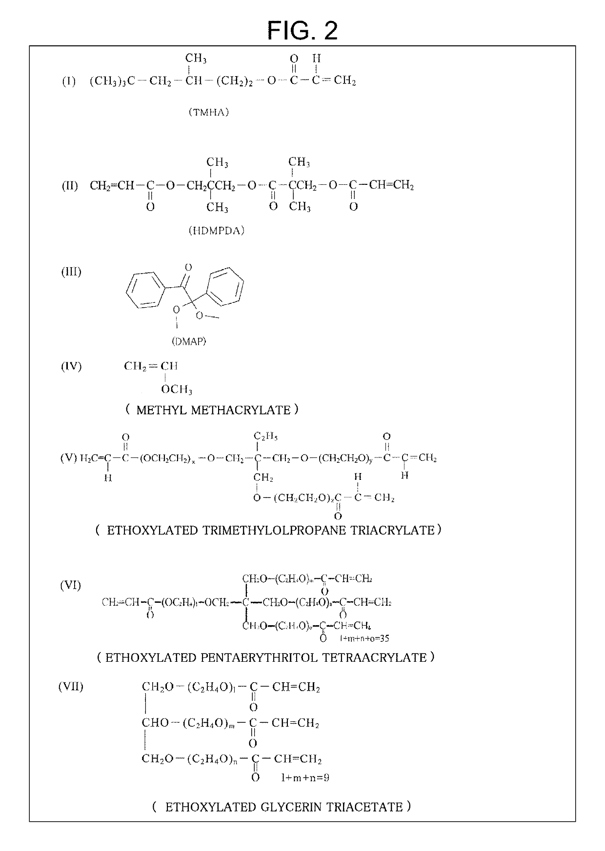
[0056]To a base liquid crystal material having a blending ratio shown in Table 2, a 1:1 mixture of A (monofunctional monomer) and B (polyfunctional monomer) as an additive was added in an amount of 5% by weight based on basic structure materials (TMHA+HDMPDA), to manufacture (film-form) a polymer / liquid crystal composite structure. The V-H test was performed with A (monofunctional monomer) being methyl methacrylate (MMA) and ethoxylated trimethylolpropane triacrylate used as B (polyfunctional monomer). The film formation conditions were as follows: a cell gap (10μ), UV (ultraviolet) irradiation (40 mW×48 s), and UV polymerization temperature (26.0° C.)

[0057]

TABLE 2Acrylic monomersLiquidBasic structureEthoxylatedAcceleration of UVcrystalmaterialstrimethylolpropanepolymerizationMaterialLC425011TMHAHDMPDAMMAtriacrylateInitiator160%10%30%——1%260% 8%24%4%4%1%360%10%22%4%4%1%470%10%12%4%4%1%550%10%32%4%4%1%

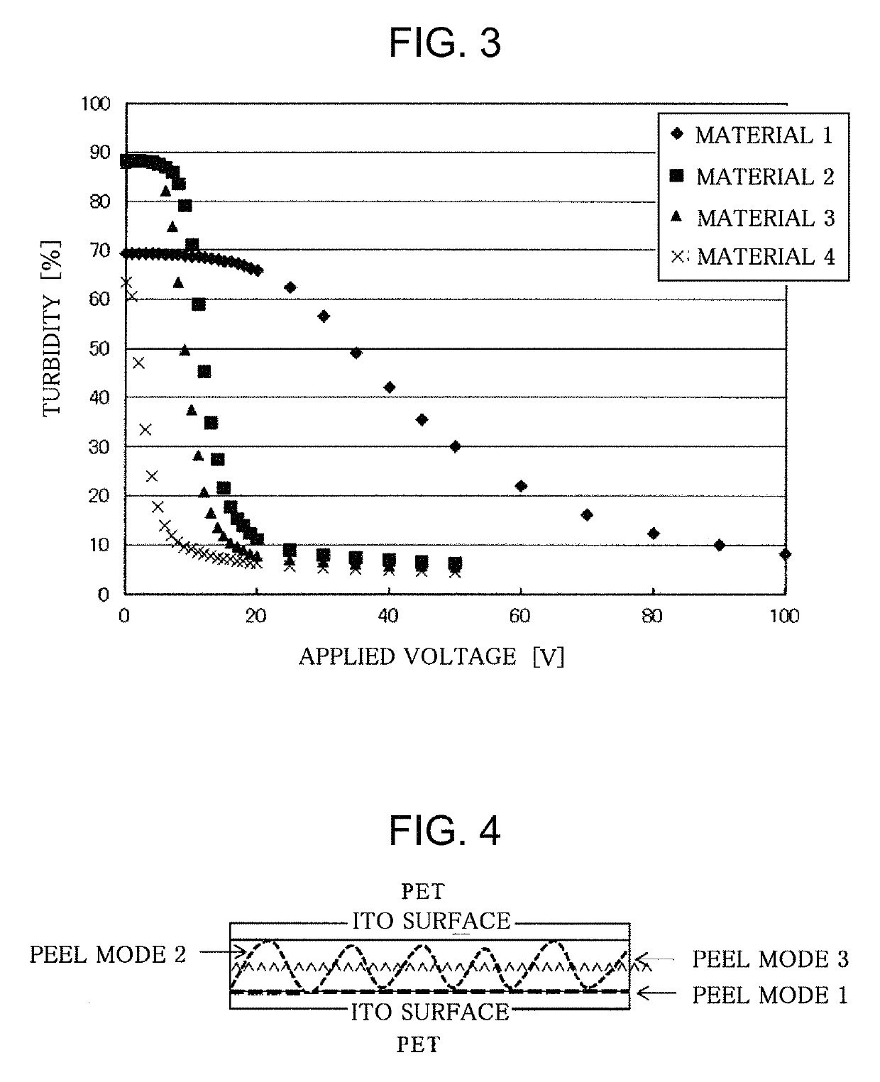
[0058]The results of the V-H test a...


PUM

PropertyMeasurementUnit
temperatureaaaaaaaaaa
viscosityaaaaaaaaaa
temperatureaaaaaaaaaa

Abstract

There is provided a light control device that solves various practical problems, including the adhesive strength between layers, of a light control device comprising a polymer / liquid crystal composite derived from a polymerizable composition comprising an acrylic monomer and ITO layers. In the light control device, ITO layers are respectively bonded to both surfaces of a polymer / liquid crystal composite material layer in which a liquid crystal material is dispersed in a polymer material obtained by polymerizing an acrylic monomer, an amount of the acrylic monomer is in the range of 30 to 45% by weight based on a total amount of the acrylic monomer and the liquid crystal material, and silane coupling agent layers are respectively interposed between the polymer / liquid crystal composite material layer and the ITO layers.

Description

TECHNICAL FIELD[0001]The present invention relates to a novel light control device preferred for use in window glass, partitions, and the like, and a method for manufacturing the same.BACKGROUND ART[0002]A light control device comprising a polymer / liquid crystal composite material comprising a polymer material typified by an acrylic acid-based polymer as a matrix with a liquid crystal material dispersed therein does not need a polarizing plate or an oriented film and can switch between a transparent state and an opaque (cloudy) state by turning on / off an electric field, unlike a conventional display comprising a liquid crystal. Therefore, it is possible to provide a light control device having a larger area, and application to building materials such as window glass and partitions is expected. Various polymer / liquid crystal materials that can constitute light control devices have been proposed [for example, Japanese Patent Laid-Open No. 2-55318 (Patent Literature 1), U.S. Pat. No. 4...

Claims


Application Information

Patent Timeline
Patent Type & Authority Patents(United States)
IPC IPC(8): G02F1/1334C09K19/30C09K19/54C08F222/10C09K19/38C09K19/12
CPCG02F1/1334C08F222/1006C09K19/3068C09K19/38C09K19/544G02F2202/28G02F2202/022C09K2019/3075C09K2019/3016C09K2019/123C09K2019/122C08F2222/1013C08F2220/1875C08F2220/1858C08F2222/1026C08F222/102C08F222/103C08F220/1811C08F220/1808
Inventor TANAKA, MASAMITSUYOSHIDA, KAZUTOSHIKONISHI, NOBUTAKE
Owner SEIKO ELECTRIC CO LTD
Features
  • Generate Ideas
  • Intellectual Property
  • Life Sciences
  • Materials
  • Tech Scout
  • Unparalleled Data Quality
  • Higher Quality Content
  • 60% Fewer Hallucinations
Learn More