Carbon fiber manufacturing device and carbon fiber manufacturing method

a carbon fiber and manufacturing device technology, applied in the direction of fibre chemical features, radio/microwave fibre treatment, textiles and papermaking, etc., can solve the problems of not being suitable for industrial production, requiring multiple magnetrons, and low heat efficiency of the pre-oxidation fiber from the external portion of the furnace heating furnace, so as to accelerate the carbonization of the fiber to be carbonized and the carbonization speed is high. , the effect of high carbon conten

Active Publication Date: 2019-04-16
TEIJIIN LTD +2
View PDF8 Cites 0 Cited by
  • Summary
  • Abstract
  • Description
  • Claims
  • Application Information

AI Technical Summary

Benefits of technology

[0090]A carbon fiber manufacturing device according to a first embodiment includes a carbonization furnace constituted by a cylindrical waveguide in which an electromagnetic distribution is in a TM mode. This carbonization furnace can perform carbonization of a fiber to be carbonized quickly in an area of the fiber having a high carbon content rate (specifically, the carbon content rate is 66 mass % or higher).
[0091]A carbon fiber manufacturing device according to a second embodiment has an adiabatic sleeve in a furnace. Thus, radiation heat generated by heating a fiber to be carbonized through irradiation with microwaves can be held in the adiabatic sleeve. As a result, carbonization of the fiber to be carbonized is accelerated. In a case in which a heater is provided at a terminal end of the adiabatic sleeve, a carbon fiber carbonized through irradiation with microwaves can be further heated. Accordingly, the quality of the carbon fiber can be further improved. In a case in which a cylindrical waveguide in which an electromagnetic distribution is in a TM mode is used as a furnace body, carbonization of the fiber to be carbonized can be performed further quickly in an area of the fiber having a high carbon content rate (specifically, the carbon content rate is 66 mass % or higher).
[0092]A carbon fiber manufacturing device according to a third embodiment has a preliminary carbonization furnace constituted by a rectangular waveguide in which an electromagnetic distribution is in a TE mode. This carbon fiber manufacturing device can perform carbonization of a fiber to be carbonized quickly in an area of the fiber having a low carbon content rate (specifically, the carbon content rate is less than 66 mass %). By combining a carbonization furnace constituted by a rectangular waveguide and a carbonization furnace constituted by a cylindrical waveguide, a carbonization process of a pre-oxidation fiber can be performed only by means of irradiation with microwaves without applying an electromagnetic wave absorber or other additives or external heating to the fiber to be carbonized. Since carbonization can be performed at atmospheric pressure in the carbon fiber manufacturing device according to each of the first to third embodiments, the fiber to be carbonized can be sequentially inserted through an inlet and an outlet formed in the furnace and carbonized.

Problems solved by technology

The firing furnace heating the pre-oxidation fiber from the external portion thereof has a low heat efficiency since the furnace body and the firing environment as well as the fiber to be carbonized are also heated in the firing furnace.
These methods have limitations such as providing a decompression unit for microwave-assisted plasma, adding an electromagnetic wave absorber or the like to a fiber to be carbonized, performing preliminary carbonization prior to heating by means of microwaves, requiring auxiliary heating, and requiring multiple magnetrons and are not suitable for industrial production.
Further, since the carbon fiber has a high radiation coefficient on its surface, it is difficult to sufficiently raise the firing temperature at the time of irradiating the fiber to be carbonized with microwaves and thereby carbonizing the fiber.
Thus, in a case of manufacturing the carbon fiber only with irradiation with microwaves, a carbon fiber having a high carbon content rate cannot be obtained.

Method used


Image

  • Carbon fiber manufacturing device and carbon fiber manufacturing method
  • Carbon fiber manufacturing device and carbon fiber manufacturing method
  • Carbon fiber manufacturing device and carbon fiber manufacturing method

Examples


first embodiment

(1) First Embodiment

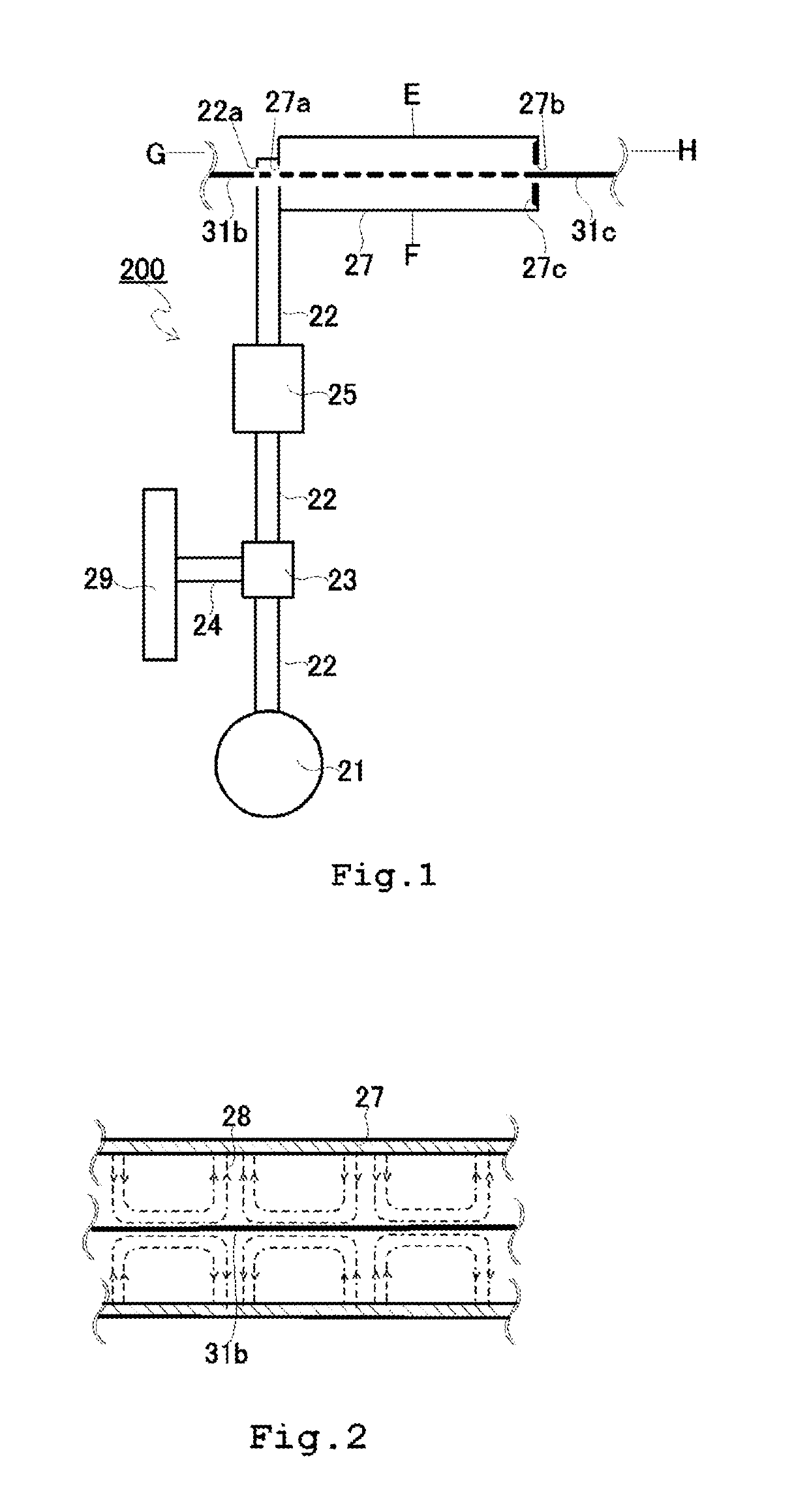
[0104]FIG. 1 illustrates a configuration example of a carbon fiber manufacturing device according to a first embodiment of the present invention. In FIG. 1, reference sign 200 refers to a carbon fiber manufacturing device, and reference sign 21 refers to a microwave oscillator. To the microwave oscillator 21, one end of a connection waveguide 22 is connected, and the other end of the connection waveguide 22 is connected to one end of a carbonization furnace 27. In this connection waveguide 22, a circulator 23 and a matching unit 25 are interposed in this order from the side of the microwave oscillator 21.

[0105]The carbonization furnace 27 is closed at one end thereof and is connected to the connection waveguide 22 at the other end thereof. The carbonization furnace 27 is a cylindrical waveguide whose cross-section along the line segment E-F is formed in a circular hollow-centered shape. One end of the carbonization furnace 27 is provided with a fiber inlet 27a to...

second embodiment

(2) Second Embodiment

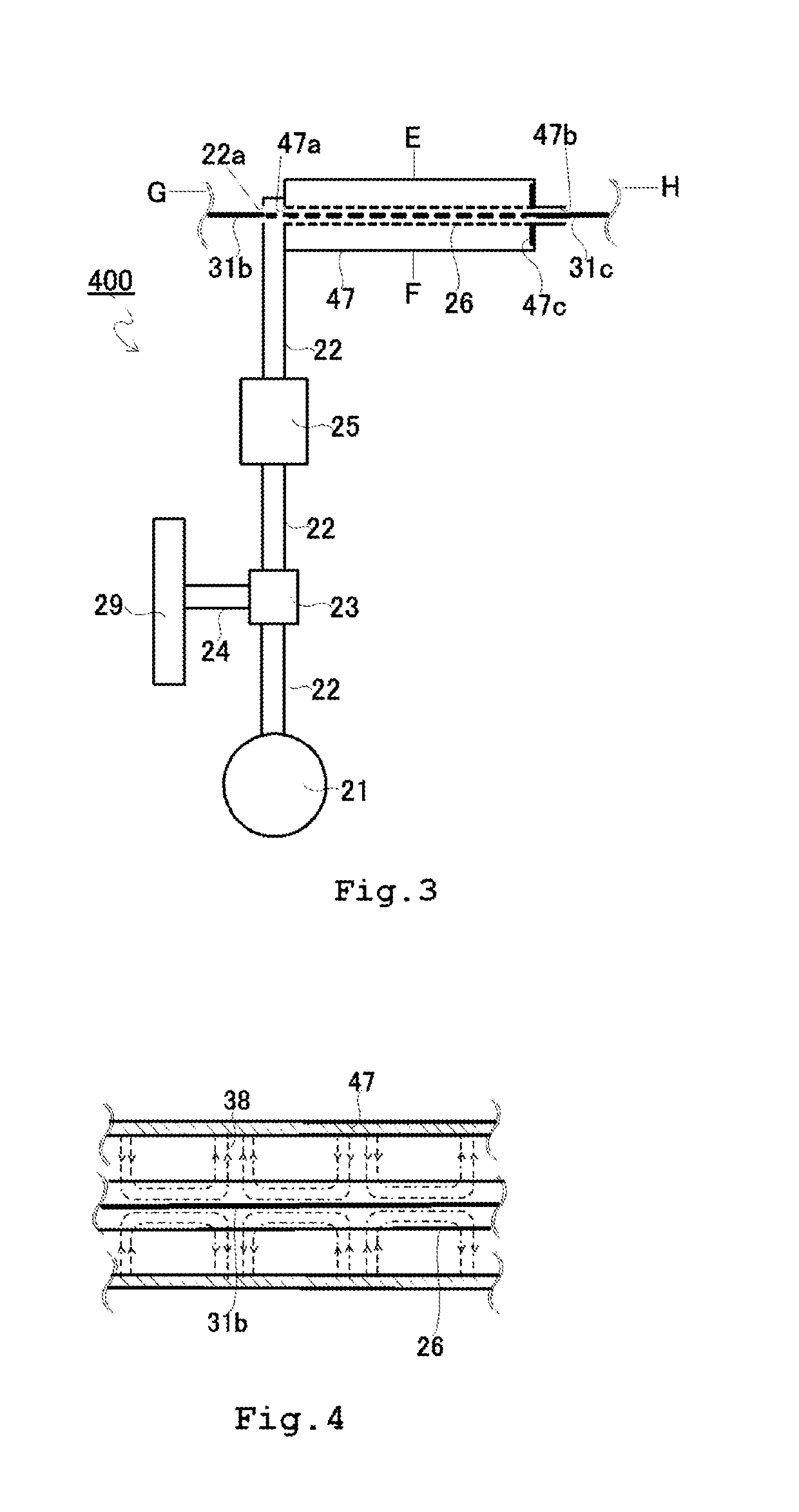
[0113]FIG. 3 illustrates a configuration example of a carbon fiber manufacturing device according to a second embodiment of the present invention. In FIG. 3, reference sign 400 refers to a carbon fiber manufacturing device. Identical components to those in FIG. 1 are shown with the same reference signs, and description of the duplicate components is omitted. Reference sign 47 refers to a carbonization furnace. The carbonization furnace 47 is a cylindrical tube closed at one end thereof and connected to the connection waveguide 22 at the other end thereof. In this carbonization furnace 47, an adiabatic sleeve 26 having a center axis parallel to a tube axis of the carbonization furnace 47 is arranged. One end of the adiabatic sleeve 26 is provided with a fiber inlet 47a to introduce a fiber to be carbonized into the carbonization furnace while the other end thereof is provided with a fiber outlet 47b to take out the carbonized fiber. A short-circuit plate 47c is a...

third embodiment

(3) Third Embodiment

[0123]A third embodiment of the present invention is a carbon fiber manufacturing device in which a preliminary carbonization furnace using microwaves is further arranged in the upstream of the carbon fiber manufacturing device according to the above first or second embodiment. FIG. 6 illustrates a configuration example of a carbon fiber manufacturing device in which a preliminary carbonization furnace using microwaves is further arranged in the upstream of the carbon fiber manufacturing device according to the first embodiment. Identical components to those in FIG. 1 are shown with the same reference signs, and description of the duplicate components is omitted. In FIG. 6, reference sign 300 refers to a carbon fiber manufacturing device, and reference sign 100 refers to a first carbonization device. Reference sign 200 refers to a second carbonization device and is equal to the carbon fiber manufacturing device 200 according to the above first embodiment (in the ...


PUM

PropertyMeasurementUnit
microwave transmittanceaaaaaaaaaa
temperatureaaaaaaaaaa

Abstract

The problem of the present invention is to provide a carbon fiber manufacturing device in which fiber to be carbonized is irradiated with microwaves and thereby heated, wherein the carbon fiber manufacturing device is compact and capable of performing carbonization at atmospheric pressure without requiring an electromagnetic wave absorber or other additives or preliminary carbonization through external heating. This carbon fiber manufacturing device (200) includes: a cylindrical furnace (27) comprising a cylindrical waveguide in which one end is closed, a fiber outlet (27b) being formed in the one end of the cylindrical waveguide and a fiber inlet (27a) being formed in the other end of the cylindrical waveguide; a microwave oscillator (21) for introducing microwaves into the cylindrical furnace (27); and a connection waveguide (22) having one end connected to the microwave oscillator (21) side and the other end connected to one end of the cylindrical furnace (27).

Description

CROSS REFERENCE TO RELATED APPLICATIONS[0001]This application is a National Stage of International Application No. PCT / JP2015 / 059512 filed Mar. 26, 2015 (claiming priority based on Japanese Patent Application Nos. 2014-074899 filed Mar. 31, 2014 and 2014-074900 filed Mar. 31, 2014), the contents of which are incorporated herein by reference in their entirety.TECHNICAL FIELD[0002]The present invention relates to a carbon fiber manufacturing device for irradiating a fiber to be carbonized with microwaves to carbonize the fiber and a carbon fiber manufacturing method using the carbon fiber manufacturing device.BACKGROUND ART[0003]A carbon fiber is superior in specific strength and specific elastic modulus than other fibers and is industrially used widely as a reinforcing fiber or the like combined with resin by taking advantage of its lightweight characteristics and excellent mechanical characteristics.[0004]Conventionally, the carbon fiber is manufactured in the following manner. Firs...

Claims


Application Information

Patent Timeline
Patent Type & Authority Patents(United States)
IPC IPC(8): D01F9/32
CPCD01F9/32D06M10/003
Inventor ZUSHI, HIROAKISUZUKI, TAKAYASUGIYAMA, JUN-ICHI
Owner TEIJIIN LTD
Why Eureka
Try Eureka