Integrated three-port bidirectional DC-DC converter for renewable energy sources

a renewable energy source and converter technology, applied in emergency power supply arrangements, instruments, process and machine control, etc., can solve the problems of reducing system efficiency, power management and system cost complexity, and the dc-dc converters known in the art are not capable of charging batteries from a common dc bus side, so as to achieve economic and efficient effects

Active Publication Date: 2019-04-16
FLORIDA STATE UNIV RES FOUND INC
View PDF6 Cites 32 Cited by
  • Summary
  • Abstract
  • Description
  • Claims
  • Application Information

AI Technical Summary

Benefits of technology

[0010]In accordance with the present invention is described, an integrated three-port bidirectional DC-DC converter that interfaces with renewable resource systems and battery systems. The three-port DC-DC converter of the present invention mainly consists of a dual active bridge (DAB) converter, which can be a dual half-bridge, dual full-bridge or dual three-phase converter for different power rating application. With no additional components added, the cost and complexity of the system does not increase.
[0015]As such, the present invention provides a distributed renewable energy system having an integrated battery backup system and an intelligent energy management system that can control the power flow among the energy sources, batteries, load and utility grid in order to achieve the most economical and efficient DC distributed energy system.

Problems solved by technology

As currently known in the art, renewable energy system converters and battery backup converters are manufactured as separate power converters, and as such, the complexity of power management and system cost is increased due to the requirement of the additional battery backup converter.
However, DC-DC converters known in the art are not capable of charging batteries from a common DC bus side, due to the unidirectional power flow between the primary and secondary side of the high frequency transformers of the DC-DC converter.
Additionally, the systems known in the prior art also result in an undesirable circulating current between the three ports of the DC-DC converter, which results in a decrease in the system efficiency.

Method used


Image

  • Integrated three-port bidirectional DC-DC converter for renewable energy sources
  • Integrated three-port bidirectional DC-DC converter for renewable energy sources
  • Integrated three-port bidirectional DC-DC converter for renewable energy sources

Examples


Embodiment Construction

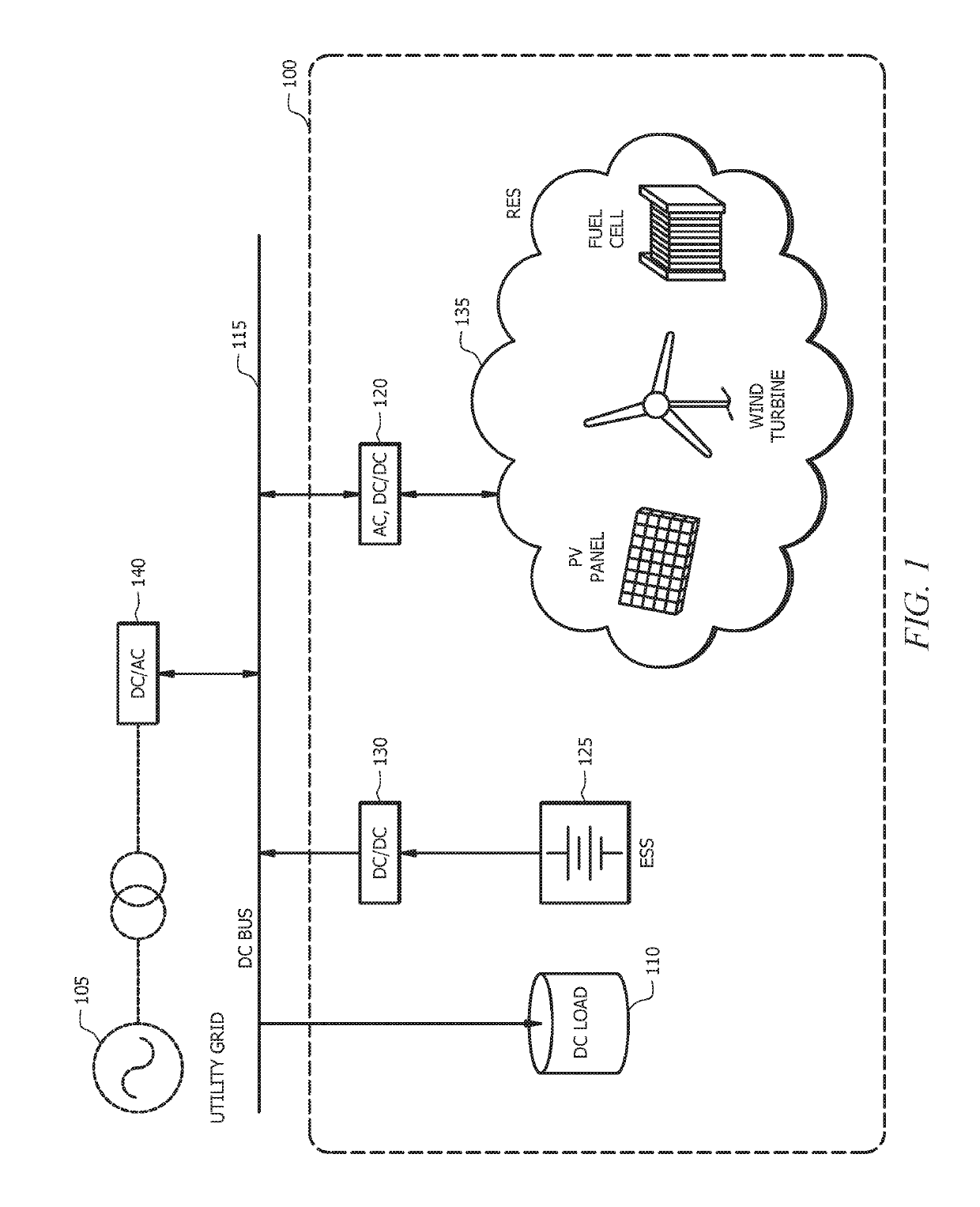
[0029]A three-port bidirectional DC-DC converter is proposed for grid-interactive renewable energy source system applications. The three-phase topology is suitable for residential power requirements. The control of the backup battery system and the renewable energy source system are naturally decoupled. In addition, the port interface with the renewable energy is current type, which can implement maximum power point tracking (MPPT) and soft switching under wide variations in the renewable energy source terminal voltage.

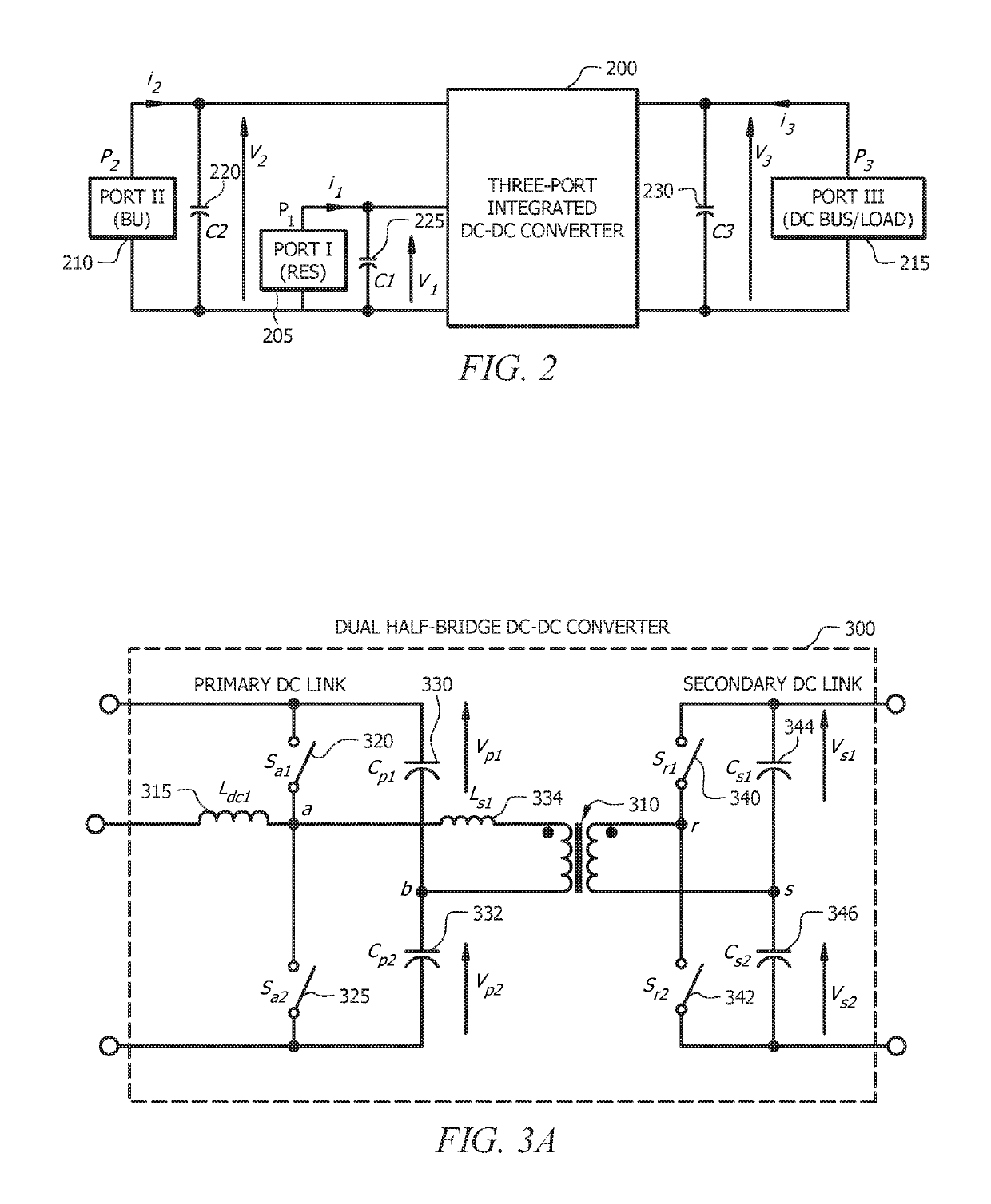
[0030]The three-port topology in accordance with an embodiment of the present invention is shown with reference to FIG. 2. As illustrated in FIG. 2, one port of the low voltage side of the proposed three-port integrated bidirectional DC-DC converter 200 is designed as a current source port that the renewable energy source (RES) 205 is connected to in order to meet the maximum power point tracking (MPPT) and voltage variation requirement. The battery backup system 210 ...


PUM


Abstract

A three-port bidirectional DC-DC converter for grid-interactive renewable energy source system applications. The three-phase topology is suitable for residential power requirements. The control of the backup battery system and the renewable energy source system are naturally decoupled. In addition, the port interface with the renewable energy is current type, which can implement maximum power point tracking (MPPT) and soft switching under wide variations in the renewable energy source terminal voltage.

Description

CROSS-REFERENCE TO RELATED APPLICATIONS[0001]This application claims priority to currently U.S. Provisional Patent Application No. 62 / 132,857, entitled “Integrated Three-Port Bidirectional DC-DC Converter For Renewable Energy Sources Application”, having a filing date of Mar. 13, 2015, the entirety of which is hereby incorporated by reference.GOVERNMENT SUPPORT[0002]This work is supported by the National Science Foundation (NSF) under the Electrical, Communications and Cyber Systems Division (ECCS) through ECCS-0641972. The Government has certain rights in the invention.FIELD OF INVENTION[0003]This invention relates to renewable energy sources systems, and more particularly, to a renewable energy source (RES) system having a battery backup.BACKGROUND OF THE INVENTION[0004]The use of renewable energy source (RES) systems, such as photovoltaic (PV) systems, rectified wind turbine systems, fuel cell systems and ultracapacitor systems, which incorporate battery backup systems, is expect...

Claims


Application Information

Patent Timeline
Patent Type & Authority Patents(United States)
IPC IPC(8): H02J9/06H02M3/24H02J7/00
CPCH02J9/06H02M3/24H02J7/0068H02M1/10H02M3/33584H02J7/34H02J2300/20H02J3/381Y02A30/60Y02B10/70H02J2300/26H02J2300/30H02J2300/28Y02E10/56
Inventor WANG, ZHANLI, HUI
Owner FLORIDA STATE UNIV RES FOUND INC
Why Eureka
Try Eureka