Joint-site structure for components to be connected by means of overlap friction welding, and method for connecting components by means of friction welding

a technology of friction welding and joint site structure, applied in the direction of non-electric welding apparatus, gas/liquid distribution and storage, applications, etc., to achieve the effect of high quality

Active Publication Date: 2019-04-30
IFA TECH
View PDF23 Cites 4 Cited by
  • Summary
  • Abstract
  • Description
  • Claims
  • Application Information

AI Technical Summary

Benefits of technology

[0016]The joint-site structure according to the invention for components to be connected by means of friction welding has the significant advantage, as compared with the aforementioned state of the art, that even thin hollow shafts can be connected with one another, without additional support elements, in precisely coaxial manner and without subsequent machining, at high quality, by means of overlap friction welding. For this purpose, the gradation of the joint sites is structured in such a manner that support of the radial process forces in the coaxial insertion region of the components is guaranteed. Furthermore, contaminants and chips resulting from the welding process are intercepted both toward the inside and toward the outside by means of the joint-site structure according to the invention. In contrast, process gases that occur due to heating can exit toward the outside without hindrance.

Problems solved by technology

However, it is also possible that these face surfaces just touch at the end of the friction-welding process.

Method used


Image

  • Joint-site structure for components to be connected by means of overlap friction welding, and method for connecting components by means of friction welding
  • Joint-site structure for components to be connected by means of overlap friction welding, and method for connecting components by means of friction welding
  • Joint-site structure for components to be connected by means of overlap friction welding, and method for connecting components by means of friction welding

Examples


Embodiment Construction

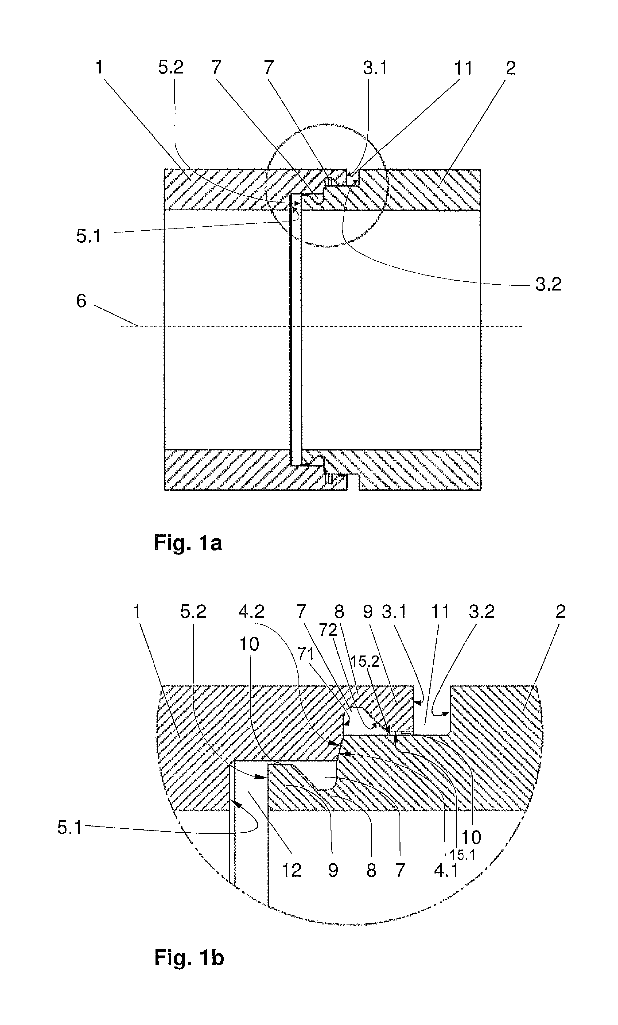
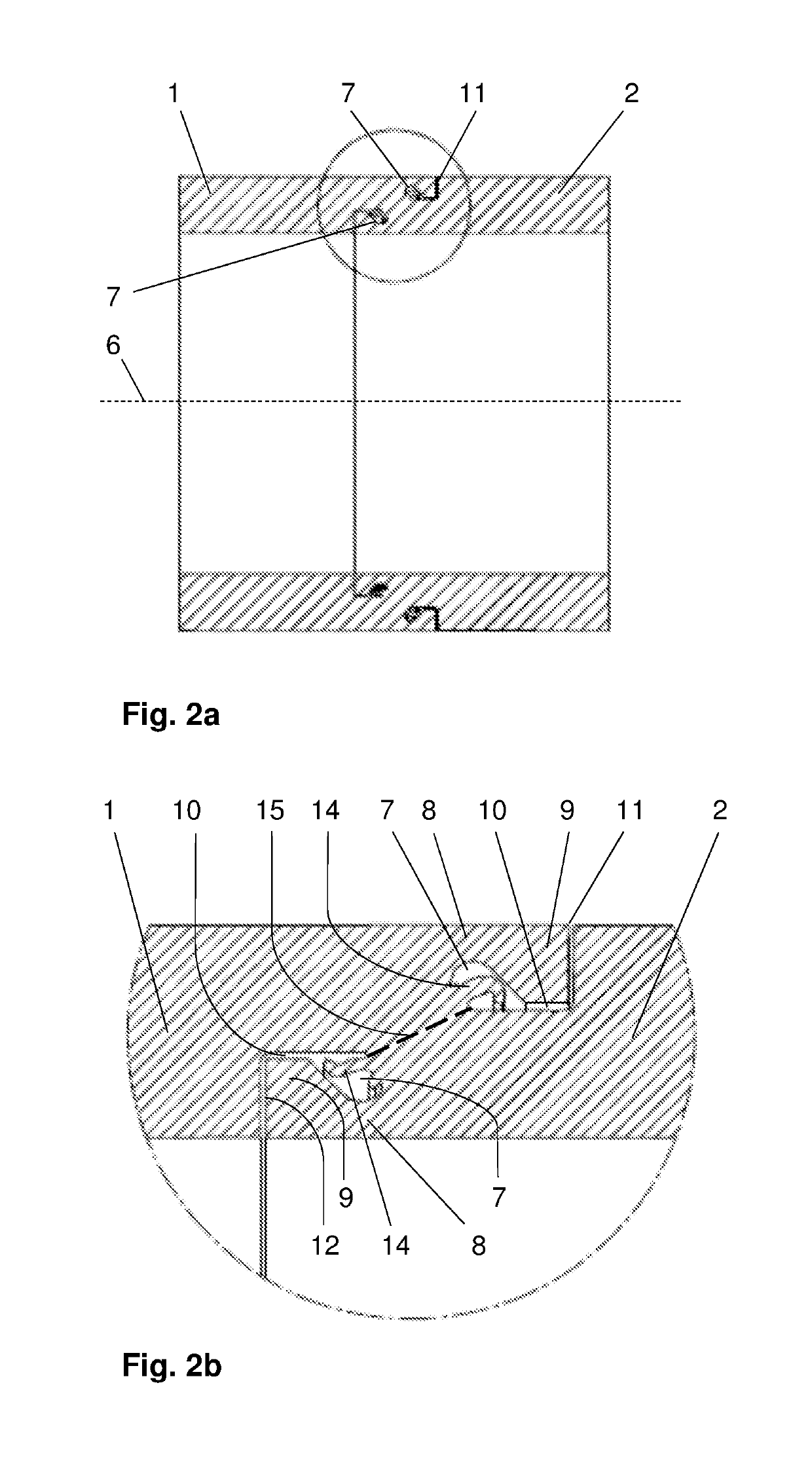
[0047]FIGS. 1a and 1b show the starting geometry of a joint-site structure according to the invention, of two pipes 1 and 2 that have rotation symmetry, are to be connected at their face sides by means of friction welding, and have the same wall thickness and weld seam preparation on both sides. The pipes can also be configured as hollow shafts, for example.

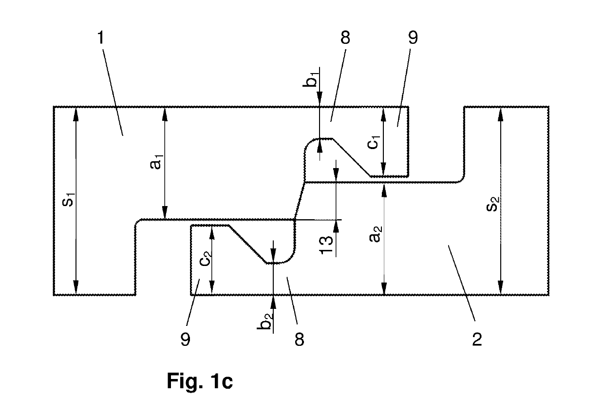
[0048]The first pipe 1 has a two-stair-step inner step on its face side that faces the second pipe 2 (this arrangement is equivalent to two inner steps having different diameters), so that on the face side, three ring-shaped face surfaces form, namely an outer face surface 3.1, a center face surface that is set back relative to the former and is referred to as a joining surface 4.1, which will still be explained below, and an inner face surface 5.1 that is once again set back axially relative to the joining surface 4.1. The joining surfaces 4.1 and 4.2 are structured conically in the present example.

[0049]The term “inner step” re...


PUM

PropertyMeasurementUnit
angleaaaaaaaaaa
joint-site structureaaaaaaaaaa
diameteraaaaaaaaaa

Abstract

A joint-site structure for components to be connected by overlap friction welding. At least one step of at least one component, on which an axially set-back ring-shaped joining surface is situated, is provided with a radial undercut, in such a manner that on the face side, a region of this step that is unchanged in diameter forms a radial support ridge, which is connected with the at least one component by way of a heat throttle that is reduced in cross-section. The length of each step is designed in such a manner that when the face surface of the one component makes contact with the ring-shaped joining surface of the other component, the other face surfaces of these components, which surfaces lie opposite one another in the same radial position, are still exposed until completion of the friction-welding process.

Description

CROSS REFERENCE TO RELATED APPLICATIONS[0001]Applicant claims priority under 35 U.S.C. § 119 of German Application No. 10 2016 005 464.6 filed May 6, 2016, the disclosure of which is incorporated by reference.BACKGROUND OF THE INVENTION1. Field of the Invention[0002]The invention proceeds from a joint-site structure for components, for example hollow shafts, which are connected with one another by means of what is called overlap friction welding, and to a method for connecting components by means of overlap friction welding.2. Description of the Related Art[0003]In overlap friction welding, the joining regions of the components to be connected with one another are structured in such a manner that after friction welding has taken place, they overlap coaxially, at least in part. As a result, at least one of the components must have at least one radial step with which it accommodates the other component, in each instance. In this regard, the step can be formed, in terms of the outside ...

Claims


Application Information

Patent Timeline
Patent Type & Authority Patents(United States)
IPC IPC(8): B23K20/12B23K33/00B23K101/06B23K101/10
CPCB23K20/129B23K20/12B23K33/006B23K2101/10B23K2101/06
Inventor SCHMICKER, DAVIDKREIBICH, MARCUSTROMMER, FRANKKRUEGER, ANDREAS
Owner IFA TECH
Why Eureka
Try Eureka