Multi-zone reactor, system including the reactor, and method of using the same

a gas phase reactor and multi-zone technology, applied in the direction of electric discharge tubes, metallic material coating processes, coatings, etc., can solve the problems of unfavorable gas phase reaction, and increased operating costs associated with device making, etc., to achieve the effect of small volume, small space occupation, and fast throughpu

Active Publication Date: 2019-04-30
ASM IP HLDG BV
View PDF2835 Cites 265 Cited by
  • Summary
  • Abstract
  • Description
  • Claims
  • Application Information

AI Technical Summary

Problems solved by technology

However, using dedicated reaction chambers requires significant capital costs and increases operating costs associated with making the devices.
In addition, processing substrates in different reaction chambers often requires a vacuum and / or air break to remove a substrate from one reaction chamber and place the substrate in another reaction chamber.
Although the introduction of different precursors is separated by time in such processes, the precursors can still undesirably mix and / or react, resulting in unwanted deposition within the reaction chamber and / or undesired particle formation.
Although these systems solve some problems associated with processing substrates in multiple reaction chambers and / or using multiple precursors within one reaction chamber, the systems still suffer drawbacks.
Horizontal transport systems require a significant amount of space, particularly floor space, for each processing region.
In addition, the total process volume of such a system is relatively large, resulting in large purge gas requirements, long purge times, and slow substrate movement to maintain desired gas separation.
Additionally, the relatively large processing region volumes can result in unwanted mixing of precursor gases.
In addition, precursor or reactant delivery schemes for horizontal transport systems are relatively complex.
Further, the configuration of these systems is relatively inflexible, due at least in part to the timing requirements for the precursor or purge gas for each processing region relative to the speed at which the substrate moves.
In addition, the mechanics of these systems can be relatively complicated and therefore such systems can be relatively unreliable and expensive to maintain.

Method used


Image

  • Multi-zone reactor, system including the reactor, and method of using the same
  • Multi-zone reactor, system including the reactor, and method of using the same
  • Multi-zone reactor, system including the reactor, and method of using the same

Examples


Embodiment Construction

[0037]The description of exemplary embodiments provided below is merely exemplary and is intended for purposes of illustration only; the following description is not intended to limit the scope of the disclosure or the claims. Moreover, recitation of multiple embodiments having stated features is not intended to exclude other embodiments having additional features or other embodiments incorporating different combinations of the stated features.

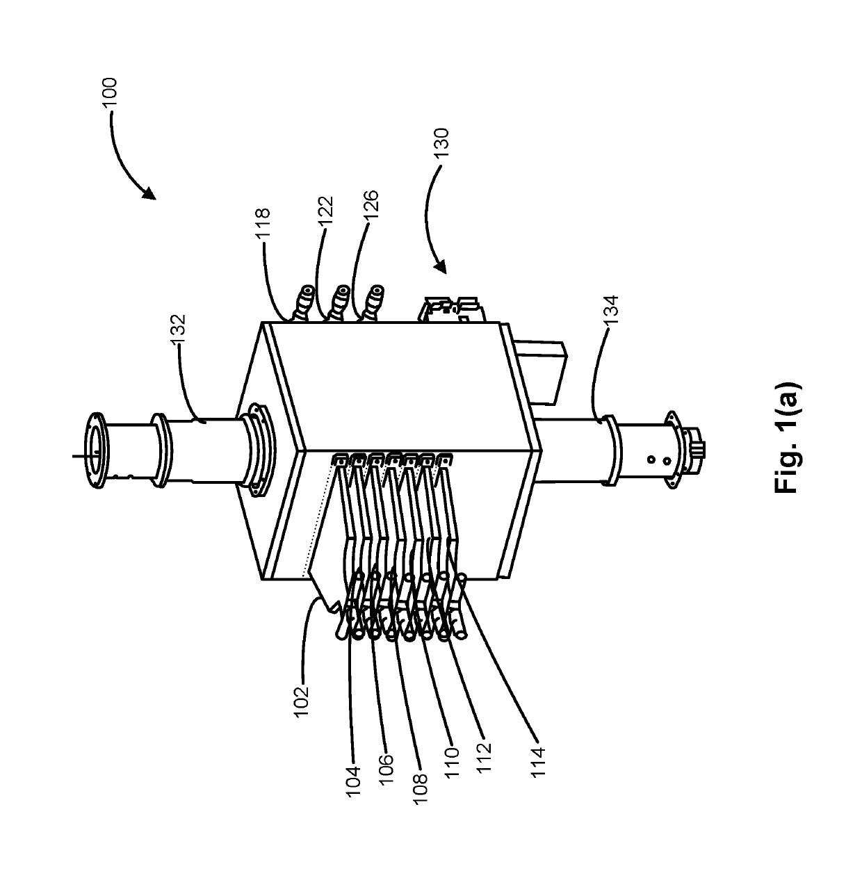
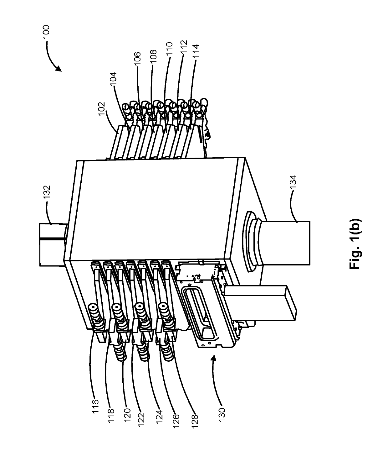
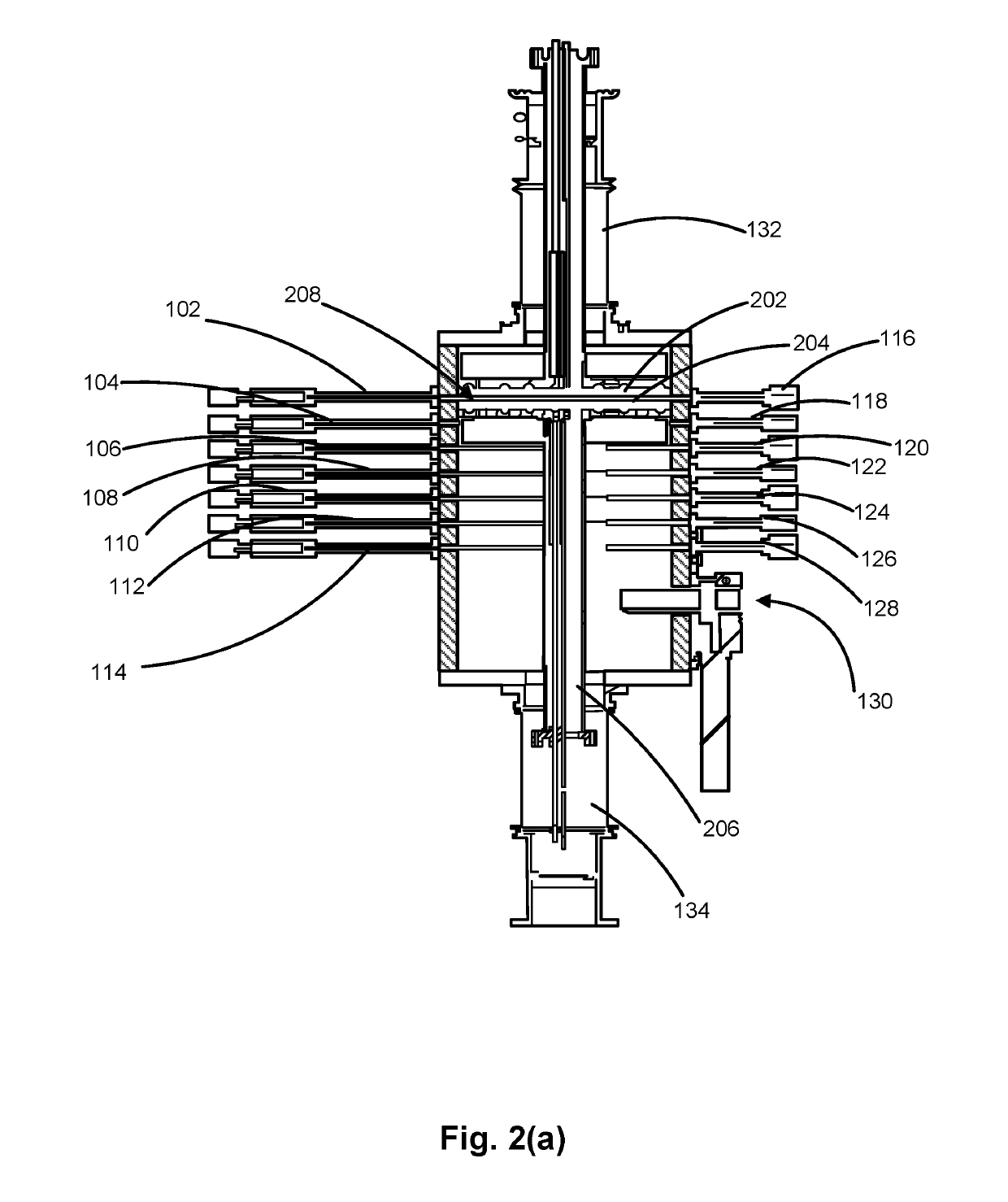
[0038]As set forth in more detail below, various embodiments of the disclosure relate to multi-zone gas-phase reactors and reactor systems that include a multi-zone gas-phase reactor and to methods of using the multi-zone gas-phase reactors and systems. The multi-zone gas-phase reactors, systems, and methods can be used for a variety of gas-phase processes, such as deposition, etch, clean, and / or treatment processes. By way of examples, a multi-zone gas-phase reactor can be used for ALD and / or ALE processes, wherein a substrate is exposed to a...


PUM

PropertyMeasurementUnit
temperaturesaaaaaaaaaa
pressuresaaaaaaaaaa
heightaaaaaaaaaa

Abstract

Multi-zone reactors, systems including a multi-zone reactor, and methods of using the systems and reactors are disclosed. Exemplary multi-zone reactors include a movable susceptor assembly and a moveable plate. The movable susceptor assembly and movable plate can move vertically between reaction zones of a reactor to expose a substrate to multiple processes or reactants.

Description

FIELD OF DISCLOSURE[0001]The present disclosure generally relates to gas-phase reactors and systems. More particularly, the disclosure relates to multi-zone gas-phase reactors, suitable for, e.g., spatial processing, to systems including the reactors, and to methods of using the same.BACKGROUND OF THE DISCLOSURE[0002]Gas-phase processes, such as chemical vapor deposition (CVD), plasma-enhanced CVD (PECVD), atomic layer deposition (ALD), atomic layer etch (ALE), and the like are often used to deposit materials onto a surface of a substrate, etch materials from a surface of a substrate, and / or clean or treat a surface of a substrate. For example, gas-phase processes can be used to deposit or etch layers on a substrate to form semiconductor devices, flat panel display devices, photovoltaic devices, microelectromechanical systems (MEMS), and the like.[0003]Typically, multiple gas-phase processes are used to form such devices. Often, each process is carried out in its own reaction chambe...

Claims


Application Information

Patent Timeline
Patent Type & Authority Patents(United States)
IPC IPC(8): H01J37/32
CPCH01J37/32899H01J37/3244H01J37/32733H01J37/32715H01J37/32513C23C16/45517C23C16/45544C23C16/45574
Inventor WHITE, CARL LOUISVERGHESE, MOHITHSHERO, ERIC JAMESDUNN, TODD ROBERT
Owner ASM IP HLDG BV
Why Eureka
Try Eureka