
Laser system and method for controlling the laser pulse shape

a laser system and temporal shape technology, applied in the field of laser system and methods for controlling the temporal shape of laser pulses, can solve the problems of non-specific thermal damage to adjacent tissue, maximum temperature differences between the target and adjacent structures, and the difficulty of controlling the effects of heat diffusion, so as to reduce the initial high laser intensity spiking

Active Publication Date: 2019-04-30
FOTONA D O O
View PDF6 Cites 1 Cited by
  • Summary
  • Abstract
  • Description
  • Claims
  • Application Information

AI Technical Summary

Benefits of technology

The present invention provides a laser system that generates a right-shifted laser pulse. This laser pulse has a lower intensity / power in the initial phase and a significantly higher intensity / power in the final stage. This helps to reduce thermal damage in deeper layers of treated tissue and the surrounding area. The laser pulse consists of a plurality of micro-pulses, which allows the treated tissue to cool down between micro-pulses, further reducing thermal damage. These technical effects improve the efficiency and safety of laser treatments.

Problems solved by technology

During a lengthy laser exposure, most of the deposited heat will diffuse away from the target structure, resulting in non-specific thermal damage to adjacent tissue.
Conversely, an adequately short laser pulse minimizes the time available for heat diffusion and confines the heating effect to the target structure, resulting in maximal temperature differences between the target and adjacent structures.
However, even with pulsed lasers, controlling the effects of heat diffusion remains a challenge.
The resulting output laser pulses which are generated by the VSP method do not only have a very short rise time, but as opposed to PFN pulses, also a very short decay time.
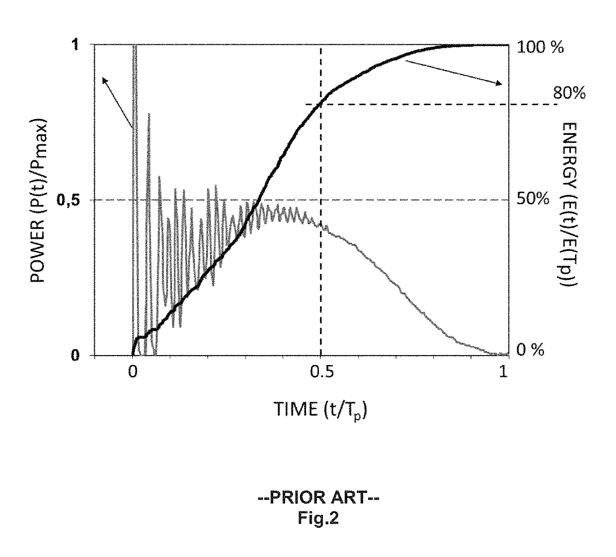
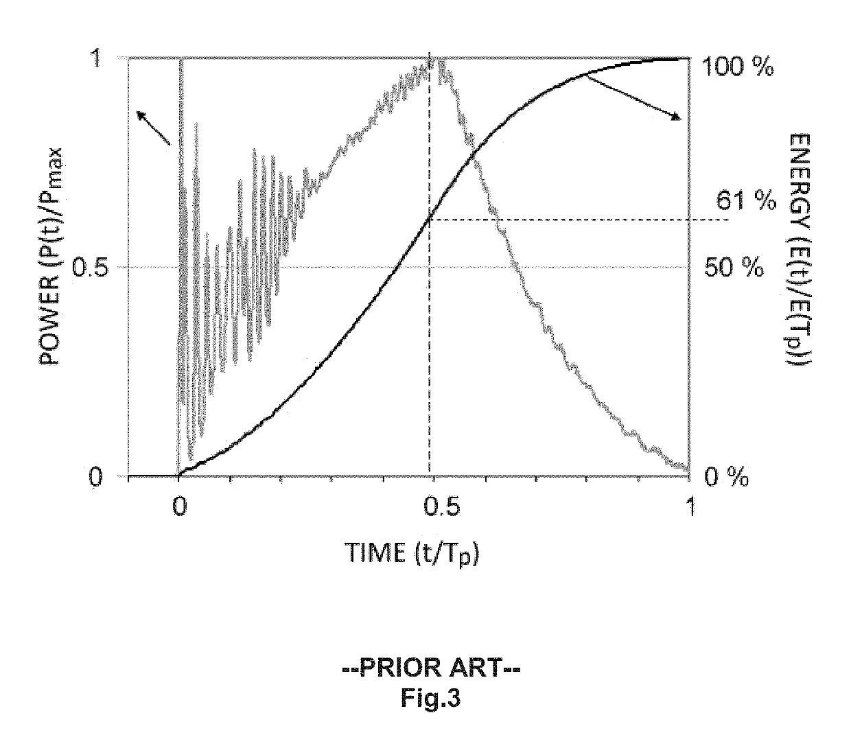
A disadvantage of prior art PFN and VSP pulse shapes is that due to the short flash lamp current ramp-up time, the laser pulse starts with sharp spikes of high intensity / power resulting in very high intensities at the beginning of the pulse, which can be an order of magnitude higher than the average pulse intensity.
In addition, high intensity oscillations at the beginning of the pulse can damage the delivery optics like output windows and fiber tips.
Prior art left-shifted pulses are disadvantageous also from the perspective of their effect on the treated tissue.
Therefore, the energy contained in the remaining decay tail of the pulse which has a suboptimal intensity is wasted and may even be harmful to the treated tissue.
The absorption of laser light leads to local heating with sudden evaporation that causes material removal.
For most medical procedures this is not desirable, since it may result in thermal damage and even tissue necrosis.
This lowers the efficiency and precision of ablation, reduces speed and causes heating of the tooth.

Method used


Image

  • Laser system and method for controlling the laser pulse shape
  • Laser system and method for controlling the laser pulse shape
  • Laser system and method for controlling the laser pulse shape

Examples


embodiment 1

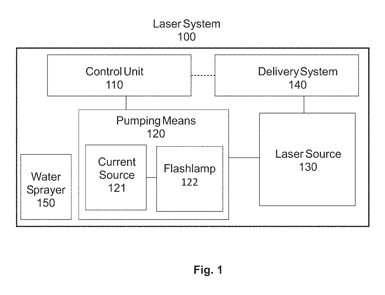
[0088]Laser system for medical treatment, comprising:[0089]a pump,[0090]wherein the laser system is adapted to be operated in pulsed operation so that at least one laser pulse of a temporally limited pulse duration (Tp) is generated,[0091]wherein said laser pulse irradiates some part of the human or animal body so that a two-dimensional laser spot S is located on the top layer of the irradiated part of the human or animal body; and[0092]wherein the pump power of the pump is modulated in such a way that the cumulative energy ES(Tp / 2) which is delivered by said laser pulse to said laser spot S during the first half of the pulse duration is less than 45% of the energy ES(Tp) which is delivered by said laser pulse to said laser spot S during the entire pulse duration Tp.

embodiment 2

[0093]Laser system according to embodiment 1, wherein the cumulative energy ES(Tp / 2) which is delivered by said laser pulse to said laser spot S during the first half of the pulse duration is less than 35% of the energy ES(Tp) which is delivered by said laser pulse to said laser spot S during the entire pulse duration Tp.

embodiment 3

[0094]Laser system according to embodiment 1, wherein the cumulative energy ES(Tp / 2) which is delivered by said laser pulse to said laser spot S during the first half of the pulse duration is less than 25% of the energy ES(Tp) which is delivered by said laser pulse to said laser spot S during the entire pulse duration Tp.


PUM


Abstract

A laser system for medical treatment is disclosed which comprises a pump, wherein the laser system is adapted to be operated in pulsed operation so that at least one laser pulse of a temporally limited pulse duration (Tp) is generated. The generated laser pulse irradiates some part of the human or animal body so that a two-dimensional laser spot S is located on the top layer of the irradiated part of the human or animal body. The pump power of the pump of the laser system is modulated in such a way that the cumulative energy ES(Tp / 2) which is delivered by said laser pulse to said laser spot S during the first half of the pulse duration is less than 45% of the energy ES(Tp) which is delivered by said laser pulse to said laser spot S during the entire pulse duration Tp.

Description

[0001]This application claims priority of European Application No. 14194451.2 filed Nov. 24, 2014, which is hereby incorporated herein by reference.FIELD OF THE INVENTION[0002]The present invention relates to a laser system and methods for controlling the temporal shape of laser pulses for achieving beneficial effects on treated parts of the human and animal body.BACKGROUND OF THE INVENTIONPrior Art[0003]Lasers have been used to treat medical conditions for several decades. Because of their properties and the range of wavelengths available, they have been used to treat a variety of indications in surgery, dentistry, dermatology, aesthetics, gynecology, ophthalmology, etc.[0004]In order to limit the undesired heat diffusion into surrounding tissue, pulsed lasers with temporally limited laser pulses are typically used for tissue treatments. When laser pulses of limited duration are used, the energy loss caused by heat diffusion during the pulse is reduced, resulting in higher treatmen...

Claims


Application Information

Patent Timeline
Patent Type & Authority Patents(United States)
IPC IPC(8): A61B18/20A61N5/067H01S3/091A61B18/24A61N5/06A61B17/00A61B18/00
CPCH01S3/0912A61B18/203A61B18/245A61B2017/00159A61N2005/067A61B2018/00476A61B2018/00577A61B2503/40A61N5/06A61B2018/00029A61N5/067
Inventor MARINCEK, MARKONENDL, JANKOMOCNIK, MATJAZMATJAZ, LUKAC
Owner FOTONA D O O
Learn More