Process for design and manufacture of cavitation erosion resistant components

a technology of cavitation erosion and manufacturing process, which is applied in the direction of computer control, program control, instruments, etc., can solve the problems of time-consuming and expensive testing, and achieve the effect of accurate surface strain characterization

Active Publication Date: 2019-05-07
HITACHI LTD
View PDF8 Cites 0 Cited by
  • Summary
  • Abstract
  • Description
  • Claims
  • Application Information

AI Technical Summary

Problems solved by technology

Yet such testing takes time and can be expensive.

Method used


Image

  • Process for design and manufacture of cavitation erosion resistant components
  • Process for design and manufacture of cavitation erosion resistant components
  • Process for design and manufacture of cavitation erosion resistant components

Examples


Embodiment Construction

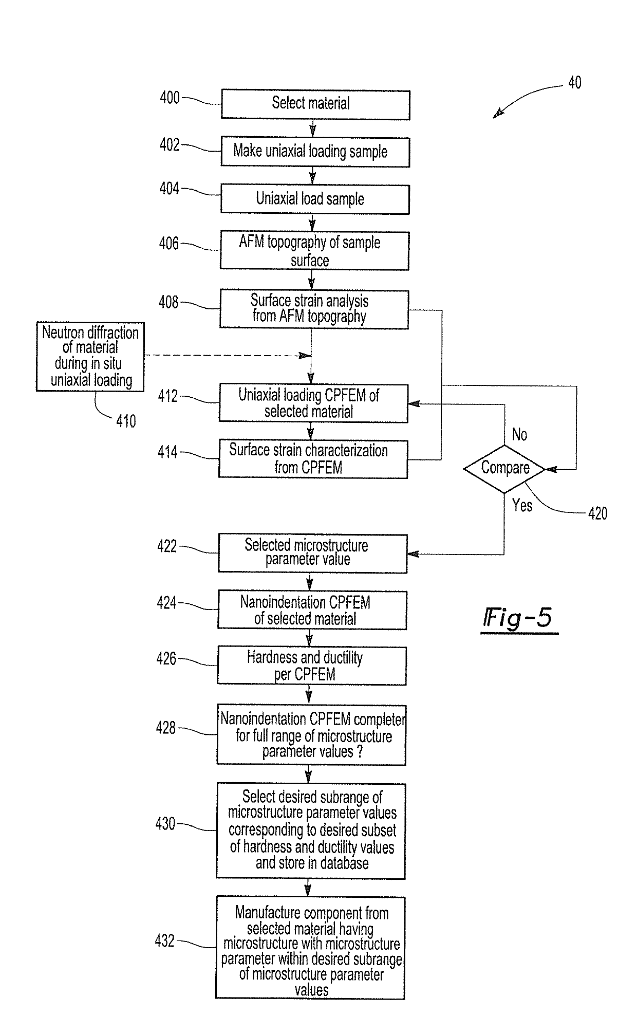
[0033]A process for designing and manufacturing a cavitation erosion (CE) resistant component is provided. The process provides a substantial improvement for material design related to cavitation erosion resistance and reduces time and cost related to the design and manufacture of anti-cavitation erosion equipment such as high pressure pumps.

[0034]The process can include determining operation conditions in a given industrial application that is susceptible to cavitation erosion. Such operation conditions can include a given liquid environment, pressure of the liquid environment, possible flow rate of the liquid environment, and the like. The process also includes selecting a material that may or may not be used in the liquid environment, such materials typically including steels, stainless steels, nickel alloys, aluminum alloys, titanium alloys, copper alloys, and the like. Once a given material or alloy is selected, a sample of the selected material, e.g. a tensile sample, is subje...


PUM

PropertyMeasurementUnit
grain sizesaaaaaaaaaa

Abstract

A process for designing and manufacturing a cavitation erosion resistant component. The process includes selecting a base material for use in a cavitation erosion susceptible environment and conducting a uniaxial loading test on a sample of the selected material. Thereafter, atomic force microscopy (AFM) topography on a surface of the tested sample is conducted and used to provide a surface strain analysis. The process also includes crystal plasticity finite element modeling (CPFEM) of uniaxial loading and CPFEM nanoindentation of the selected material over a range of values for at least one microstructure parameter. A subrange of microstructure parameter values that correlate to CPFEM nanoindentation results that provide increased CE resistance is determined. Finally, a component having an average microstructure parameter value that falls within the subrange of microstructure parameter values is manufactured.

Description

FIELD OF THE INVENTION[0001]The present invention is directed to a process for designing and manufacturing a component that is resistant to cavitation erosion, and in particular to a process for designing and manufacturing a cavitation erosion resistant component using crystal plasticity finite element modeling.BACKGROUND OF THE INVENTION[0002]Cavitation erosion (CE) is caused by the formation and collapse of vapor bubbles in a liquid near a metallic component surface. For example, FIG. 1 provides a series of figures in which the cavitation erosion mechanism is shown. In FIG. 1a, a vapor bubble ‘b’ forms on an outer film ‘f’ that is present on a surface of a matrix material ‘m’. Upon collapse of the vapor bubble b as illustrated in FIG. 1b, the film f experiences a local failure or opening ‘o’. In addition, a small defect ‘d’ can be formed within the matrix material ‘m’ and the film ‘f’ may or may not form over the defect site as shown in FIG. 1c. The defect site ‘d’ can act as or i...

Claims


Application Information

Patent Timeline
Patent Type & Authority Patents(United States)
IPC IPC(8): C22F1/04C22F1/10C21D8/00G05B19/4099C22C1/00C22F1/08C22F1/18C22F1/06
CPCG05B19/4099C21D8/005C22C1/00C22F1/04C22F1/08C22F1/10C22F1/183C22F1/06G05B2219/49007G05B2219/35134
Inventor ZHENG, LILIYUAN, WEIBADARINARAYAN, HARSHA
Owner HITACHI LTD
Why Eureka
Try Eureka