Supercharge Your Innovation With Domain-Expert AI Agents!

Delay circuit for a radio signal with filter circuitry to linearize a phase shift of an output signal relative to an input

a delay circuit and radio signal technology, applied in the field of interference processing, can solve the problems of inability to communicate, signal contains wideband noise, and degrade communication quality, and achieve the effect of improving delay stability and efficient removal

Active Publication Date: 2019-05-21
AIRBUS DS SLC
View PDF6 Cites 0 Cited by
  • Summary
  • Abstract
  • Description
  • Claims
  • Application Information

AI Technical Summary

Benefits of technology

The present invention describes a device that can physically remove interference in a signal by adjusting the phase-shift, amplitude, and time offset of a compensation signal. This allows for efficient removal of interference across a wide range of frequencies. Additionally, the invention includes a delay circuit that provides a consistent delay across a wide frequency range and improved delay stability as a function of frequency. This allows for better checking of the phase-shift linearity of the output signal. The invention also includes a processing circuit or compensation circuit that includes a delay circuit, which enables accurate checking of the time offset of the signal on a widened frequency range.

Problems solved by technology

Two radio communication systems can thus interfere, which degrades communication quality and can even make communications impossible.
Indeed, the transmitted signal contains a wideband noise, this noise type being amplified by the non-linearities of the transmission chain.
The wideband noise and the frequency band of the piece of receiver equipment therefore overlap each other on all or part of the bandwidth, which degrades the reception quality.
Besides, the presence of a radio signal transmitted at a strong power at a low distance from a receiver can desensitise said receiver, even if the transmission and reception frequency bands are different.
A difference in the time delays between the direct signal and the signal transmitted by the transmitter and between the compensation signal and the signal transmitted by the transmitter strongly degrades the performance of this device type.
The cancellation of the direct signal by the compensation signal thus only intervenes in a reduced frequency range, making the device inefficient in cancelling the wideband noise transmitted by the transmitter or in cancelling in the entire transmission channel the signal transmitted from a high rate communication signal.
These filters represent however a high cost and their pass frequency and rejection bands are hardly modifiable in an operating mode.

Method used


Image

  • Delay circuit for a radio signal with filter circuitry to linearize a phase shift of an output signal relative to an input
  • Delay circuit for a radio signal with filter circuitry to linearize a phase shift of an output signal relative to an input
  • Delay circuit for a radio signal with filter circuitry to linearize a phase shift of an output signal relative to an input

Examples


Embodiment Construction

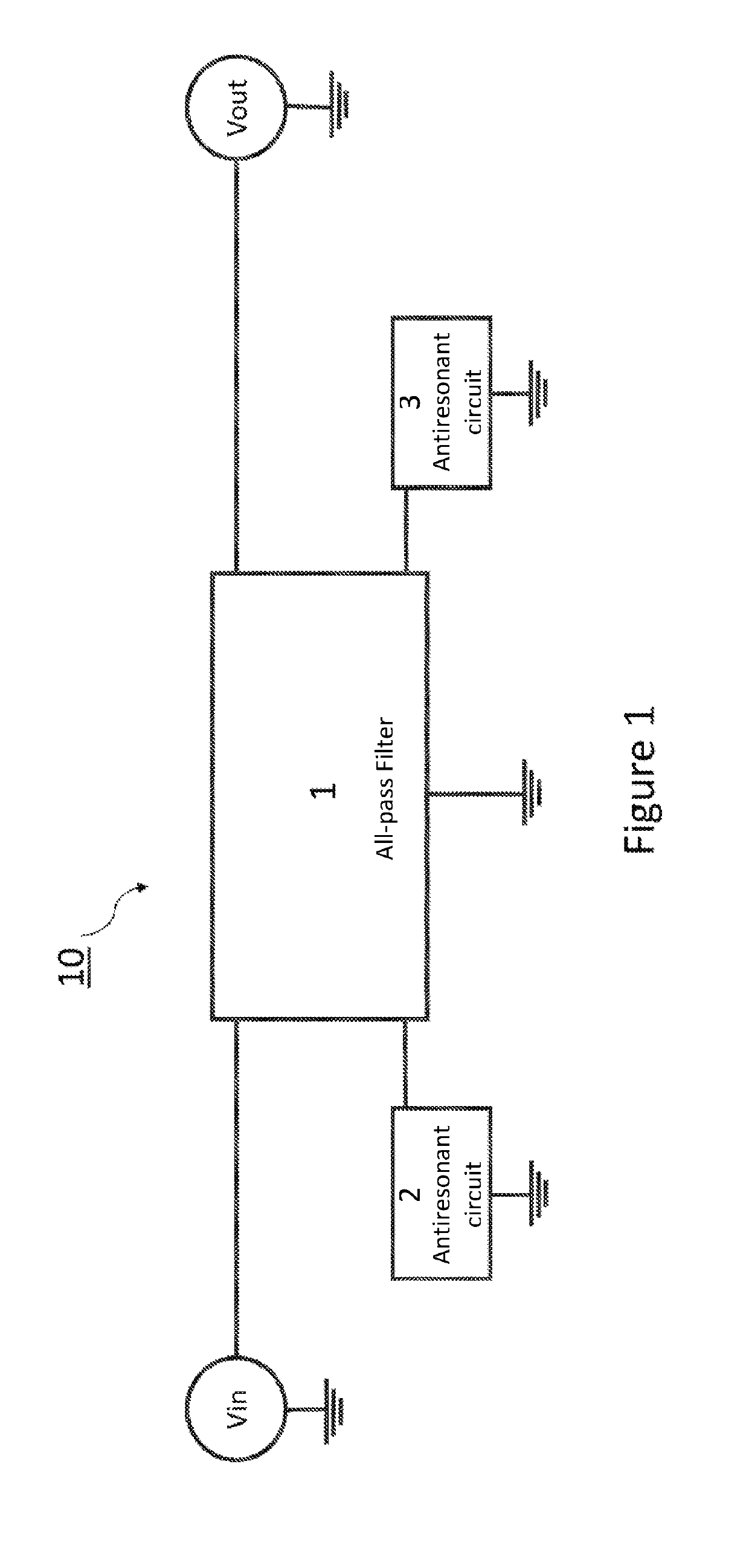
[0071]FIG. 1 illustrates the delay circuit 10 according to the invention. The circuit 10 is a circuit capable of outputting a signal Vout identical to the signal Vin but with a time offset.

[0072]The delay circuit 10 according to the invention is comprised of an all-pass filter 1 and two antiresonant circuits 2, 3. The all-pass filter 1 has a given central frequency f0. The first and second antiresonant circuits 2 and 3 have the respective centre frequencies f1 and f2.

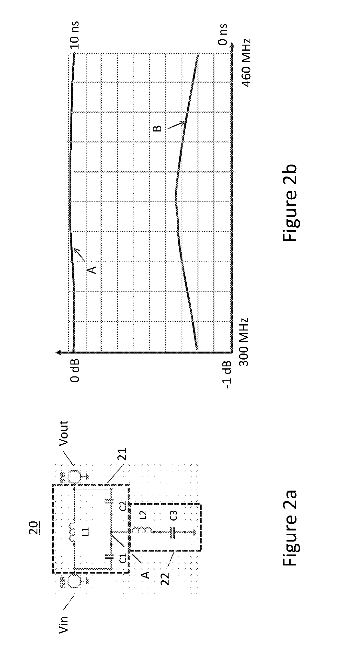
[0073]An exemplary all-pass circuit 20 known to those skilled in the art is represented in FIG. 2a. This circuit comprises a stopper circuit 21 and a resonant circuit 22. FIG. 2b shows the characteristics of this filter on the frequency range between 300 MHz and 460 MHz.

[0074]A way to qualitatively understand the operation of the circuit 20 is the following one. The stopper circuit 21 formed by the capacitances C1 and C2 associated in parallel with an inductor (also called induction coil) L1 has a cut-off frequency fa. ...


PUM


Abstract

A delay circuit for time offsetting an input radiofrequency signal, includes an all-pass filter having a given central frequency to linearize a phase-shift of an output signal relative to the input signal as a function of the frequency on a first frequency range; and first and second antiresonant circuits having respectively first and second central frequencies, the all-pass filter and the antiresonant circuits configured to linearize the phase-shift of the output signal relative to the input signal as a function of the frequency on a second frequency range including the first range. The difference between first and second central frequencies is less than 30% of the value of one of both frequencies, the difference between the first central frequency and the given central frequency of the all-pass filter is less than 30% of the value of a highest frequency between the first central frequency and the given central frequency.

Description

CROSS-REFERENCE TO RELATED APPLICATIONS[0001]This application claims priority to French patent application number 1655129 filed Jun. 6, 2016, the content of which is incorporated herein by reference in its entirety.FIELD[0002]The field of the invention relates to systems for transmitting and receiving radio communication waves. The invention is in particular concerned with interference processing between different radio communication systems located at a low distance from each other, as for example radio communication systems installed in a same vehicle and having their radio antennas on the roof of said vehicle.STATE OF THE ART[0003]Emergency or security services are led to use different pieces of radio communication equipment to meet their multiple communication needs. A vehicle can thus be equipped with a terminal such as a LTE terminal having radio communication channels having a wide frequency band and a high rate as well as a terminal such as a TETRAPOL terminal having radio c...

Claims


Application Information

Patent Timeline
Patent Type & Authority Patents(United States)
IPC IPC(8): H04B1/40H03H7/19H04B1/12H04B1/10H04B3/23H03H7/32H04B1/525H03H7/20H03H7/25
CPCH04B1/1036H03H7/19H03H7/325H04B1/525H04B3/232H04B1/12H03H7/255H03H7/20
Inventor GAGEY, OLIVIER
Owner AIRBUS DS SLC
Features
  • R&D
  • Intellectual Property
  • Life Sciences
  • Materials
  • Tech Scout
  • Unparalleled Data Quality
  • Higher Quality Content
  • 60% Fewer Hallucinations
Learn More