Method for the production of air gases by the cryogenic separation of air

a technology of air gas and cryogenic separation, applied in the field of methods, can solve the problems of inefficiency and pipeline operation, and achieve the effects of minimal pressure loss, reduced pressure loss, and significant power saving

Active Publication Date: 2019-05-28
LAIR LIQUIDE SA POUR LETUDE & LEXPLOITATION DES PROCEDES GEORGES CLAUDE
View PDF6 Cites 25 Cited by
  • Summary
  • Abstract
  • Description
  • Claims
  • Application Information

AI Technical Summary

Benefits of technology

[0009]In one embodiment, the invention can include a method for adjusting the production pressure(s) of the air gases (e.g., nitrogen and oxygen) to follow the pressure of the pipeline, thereby reducing power consumption when the pipeline pressure decreases.
[0066]the apparatus can have an absence of a GOX feed valve configured to reduce the difference between the pipeline pressure PPL and the delivery pressure PDO;

Problems solved by technology

However, pipelines do not operate at constant pressures.
However, this method suffers from inefficiencies anytime the pipeline pressure is below that of the design pressure of the ASU.

Method used


Image

  • Method for the production of air gases by the cryogenic separation of air
  • Method for the production of air gases by the cryogenic separation of air
  • Method for the production of air gases by the cryogenic separation of air

Examples


Embodiment Construction

[0074]While the invention will be described in connection with several embodiments, it will be understood that it is not intended to limit the invention to those embodiments. On the contrary, it is intended to cover all the alternatives, modifications and equivalence as may be included within the spirit and scope of the invention defined by the appended claims.

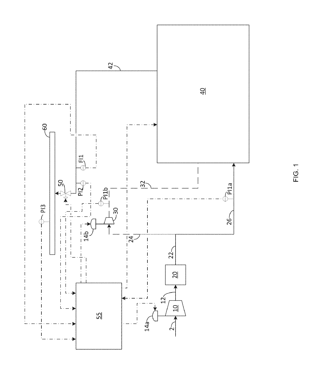
[0075]Now turning to FIG. 1. Air 2 is introduced into main air compressor 10 and compressed, preferably to a pressure of at least 55 psig to 75 psig (or around 5 psig higher than the pressure of the higher pressure column). The resulting compressed humid air stream 12 is then purified of water and CO2 in front end purification system 20, thereby producing dry air stream 22. In one embodiment, all of dry air stream 22 passes via line 26 into cold box 40. The pressure of dry air stream 22 is measured by first pressure indicator PI1a. Within cold box 40, the air is cooled and cryogenically treated in order to separate the air int...


PUM


Abstract

A method for the production of air gases by the cryogenic separation of air can include the steps of sending a purified and compressed air stream to a cold box under conditions effective for cryogenically separating the air stream into an oxygen product and nitrogen using a system of columns, wherein the purified and compressed air stream is at a feed pressure when entering the system of columns; withdrawing the oxygen product at a product pressure; delivering the oxygen product at a delivery pressure to an oxygen pipeline, wherein the oxygen pipeline has a pipeline pressure; wherein during the second mode of operation, the method can include monitoring the pipeline pressure; and reducing the difference between the pipeline pressure and the delivery pressure. By operating the method in a dynamic fashion, a power savings can be realized in instances in which the pipeline pressure deviates from its highest value.

Description

RELATED APPLICATIONS[0001]This application claims priority to U.S. Provisional Application Ser. No. 62 / 356,962 filed on Jun. 30, 2016, which is hereby incorporated by reference in its entirety.TECHNICAL FIELD OF THE INVENTION[0002]The present invention generally relates to a method and apparatus for efficiently operating an air separation plant that feeds at least one of its products to a pipeline.BACKGROUND OF THE INVENTION[0003]Air separation plants separate atmospheric air into its primary constituents: nitrogen and oxygen, and occasionally argon, xenon and krypton. These gases are sometimes referred to as air gases.[0004]A typical cryogenic air separation process can include the following steps: (1) filtering the air in order to remove large particulates that might damage the main air compressor; (2) compressing the pre-filtered air in the main air compressor and using interstage cooling to condense some of the water out of the compressed air; (3) passing the compressed air stre...

Claims


Application Information

Patent Timeline
Patent Type & Authority Patents(United States)
IPC IPC(8): F25J3/04
CPCF25J3/04412F25J3/0409F25J3/04084F25J3/04527F25J3/04836F25J3/04296F25J2290/60
Inventor KONG, PAULPHAM-HUY, MINHYIP, WENDY
Owner LAIR LIQUIDE SA POUR LETUDE & LEXPLOITATION DES PROCEDES GEORGES CLAUDE
Why Eureka
Try Eureka