Method and device for real-time mapping and localization

a technology of localization and localization, applied in the field of localization and mapping, can solve the problems of low position accuracy and significant drift, inability to generate map information in inertial systems, and not suitable for positioning and navigation purposes,

Active Publication Date: 2019-05-28
EURO ATOMIC ENERGY COMMUNITY (EURATOM)
View PDF11 Cites 15 Cited by
  • Summary
  • Abstract
  • Description
  • Claims
  • Application Information

AI Technical Summary

Benefits of technology

[0016](b) constructing, using the (3D) scanner data for each of a plurality of poses of the laser range scanner, each pose having an associated point cloud defined by the scanner data, a map presentation, the map presentation having a data structure configured for random sample access thereto in constant time, fast nearest neighbor search and scalability over large areas, and
[0022]In a particularly preferred embodiment, the data structure is set to natively handle 3D points and is based on a hybrid structure composed by a sparse voxelized structure used to index a (compact dense) list of features in the map presentation, allowing constant time random access in voxel coordinates independently from the map size and efficient storage of the data with scalability over the explored space.
[0023]In a still further preferred embodiment, the data structure may maintain five different representations of the data stored, thereby granting consistency between internal data representations after each map update, the five representations being
[0050]To improve overall system robustness, it is considered to combine the scanner tracking with an odometer (e.g. using the odometer module as described in step (c)(i) of the method of the first aspect above), such that after a pose has been estimated, its associated points in world coordinates are stored into a kd-tree (thus creating an odometer map), given a new acquisition (point cloud acquired) by the laser range scanner, (i.e. when a registration algorithm creates the sets of points) (PiW), it looks for nearest neighbors in both the 3D reference map (qiM,niM) and in the previously fixed point cloud (odometer map) (qio,nio), wherein correspondences are defined as:

Problems solved by technology

They are small and inexpensive, however the position accuracy is low and drifts significantly over time.
Furthermore, inertial systems do not generate map information.
Therefore, they are only suitable for positioning and navigation purposes, not for map generation.
Furthermore, they do not generate map information.
Therefore, they are only suitable for positioning and navigation purposes, not for map generation.
However, the system does not provide immediate feedback to the user, as data processing is carried out off-line.
Again, it does not provide for on-line visualization.
Almost all these solutions lack real-time / on-line visualization and more importantly they do not allow for any direct user interaction on the acquiring and processing steps.

Method used


Image

  • Method and device for real-time mapping and localization
  • Method and device for real-time mapping and localization
  • Method and device for real-time mapping and localization

Examples


Embodiment Construction

[0078]As already mentioned previously, one of the main advantages of preferred embodiments of the present invention as herein described lies in the concept of providing real-time change analysis and monitoring in GPS-denied (e.g. indoor) environments. The user is able to inspect a facility and view the changes on a handheld device as he walks through the facility. The preferred underlying methodologies and algorithms are summarized below and further detailed thereafter.

[0079]A basic workflow for a previously unknown (unscanned) location requires in principle two steps: (A) the construction of a 3D reference model at T0 and (B) the localization, tracking and change analysis based on 3D reference model at T1. When revisiting such a location or in cases where an appropriate map already exists, step (B) will be sufficient.

[0080](A) Construction of 3D Reference Map

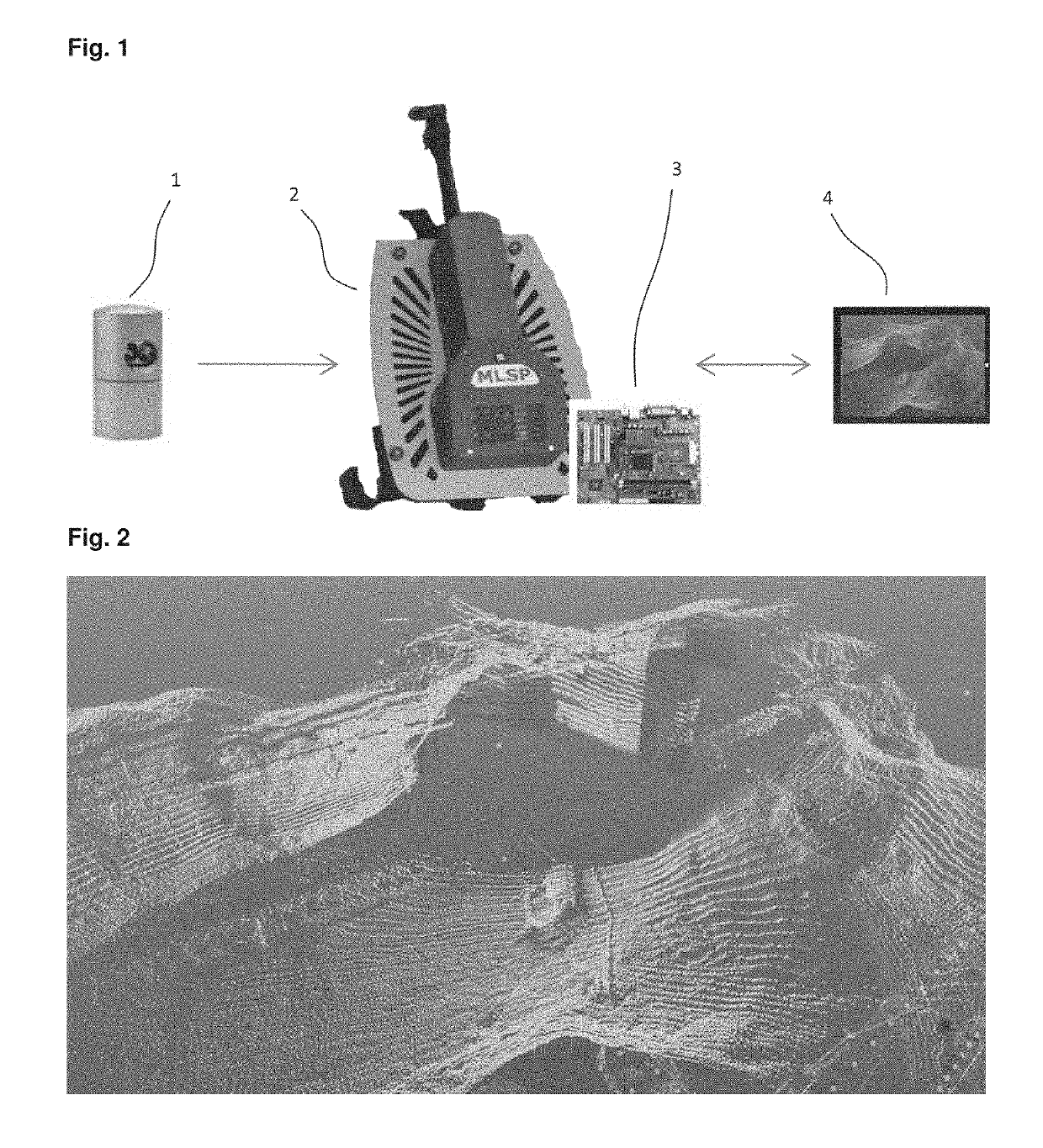
[0081]The 3D reference map is built using a 3D SLAM (Simultaneous Localization And Mapping) implementation based on a mobile ...


PUM


Abstract

A method for constructing a 3D reference map useable in real-time mapping, localization and / or change analysis, wherein the 3D reference map is built using a 3D SLAM (Simultaneous Localization And Mapping) framework based on a mobile laser range scanner A method for real-time mapping, localization and change analysis, in particular in GPS-denied environments, as well as a mobile laser scanning device for implementing said methods.

Description

CROSS-REFERENCE TO RELATED APPLICATIONS[0001]This application is a continuation of International Patent Application Number PCT / EP2016 / 057935 filed on Apr. 11, 2016 which claims priority to European Patent Application Number 15163231.2 filed Apr. 10, 2015, the contents of which are incorporated herein by reference in their entirety.TECHNICAL FIELD[0002]The present invention generally relates to localization and mapping, especially in GPS-denied environments, such as indoors.BACKGROUND ART[0003]Different solutions have been described or are commercially available to allow for acquire environments for purposes such as localization or mapping. Different approaches have given rise to different solutions.[0004]Among these, a number of commercial and prototype indoor navigation systems are based on inertial sensors (e.g. DLR's FootSLAM, Chirange Geospatial Indoor Tracking). They are small and inexpensive, however the position accuracy is low and drifts significantly over time. Furthermore,...

Claims


Application Information

Patent Timeline
Patent Type & Authority Patents(United States)
IPC IPC(8): G01S7/48G06T7/20G05D1/02G01S17/42G01C21/20G01S17/89G06T7/579G06T15/08G06T15/10
CPCG06T15/10G01C21/206G01S7/4808G01S17/42G01S17/89G06T7/20G06T7/579G06T15/08G05D1/0272G06T2215/16G06T2200/04G06T2207/10028G05D1/024G05D1/0274
Inventor SEQUEIRA, VITORWOLFART, ERIKTADDEI, PIERLUIGICERIANI, SIMONESANCHEZ-BELENGUER, CARLOSPUIG ALCORIZA, DAVID
Owner EURO ATOMIC ENERGY COMMUNITY (EURATOM)
Why Eureka
Try Eureka