Electric power tool
a technology of electric power tools and impulse tools, which is applied in the direction of power driven tools, wrenches, screwdrivers, etc., can solve the problems of compact tool construction compared to the prior art arrangement, and achieve the effects of improving connection, ensuring safety, and ensuring safety
- Summary
- Abstract
- Description
- Claims
- Application Information
AI Technical Summary
Benefits of technology
Problems solved by technology
Method used
Image
Examples
first embodiment
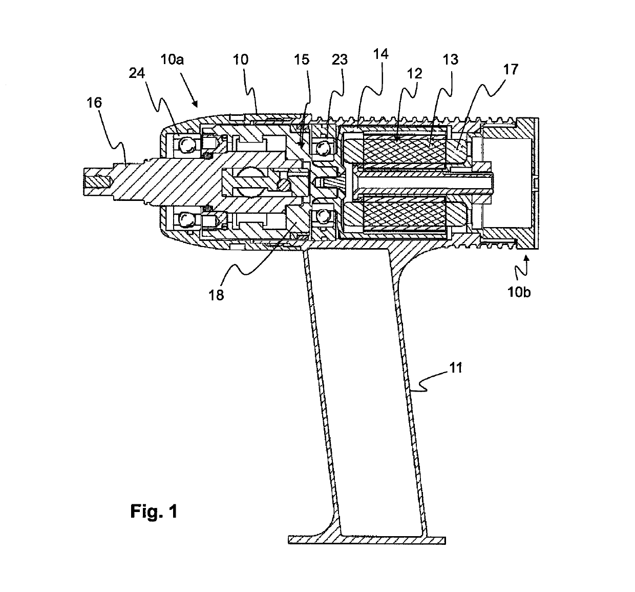
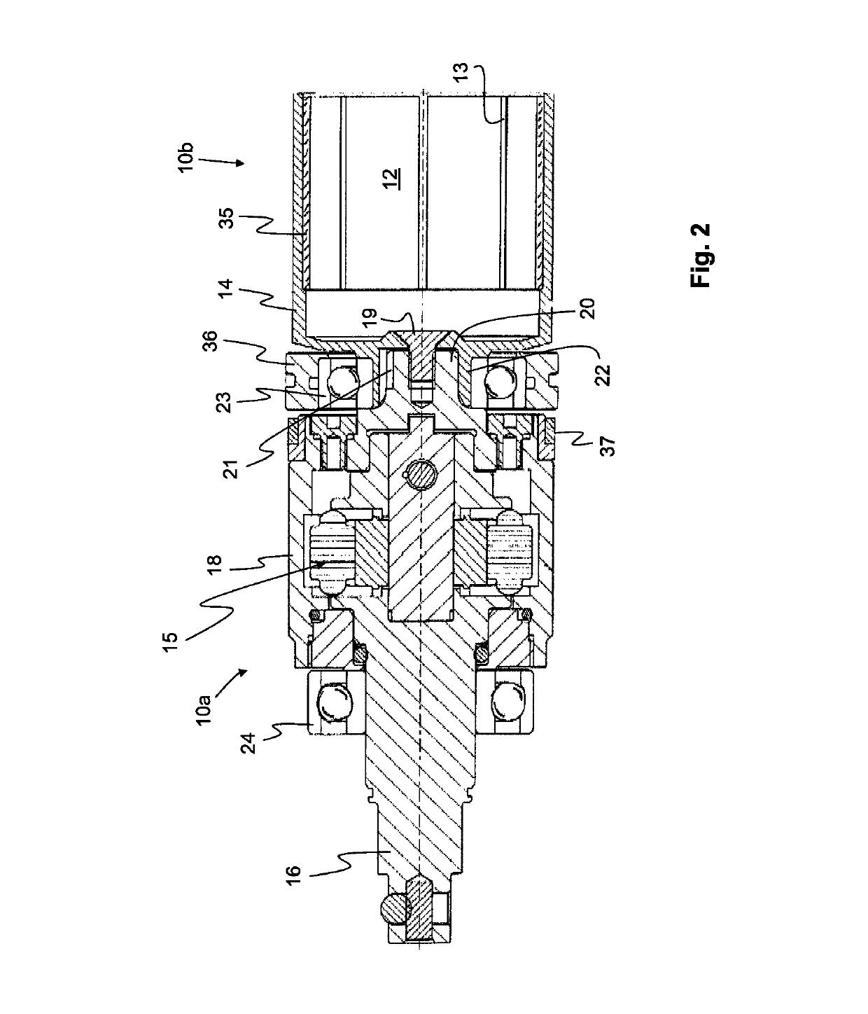
[0022]A detailed view of the motor 12 and the pulse unit 15 of the invention is shown in FIG. 2. An advantage of the invention is that the motor rotor 14 and the pulse unit 15 are intimately assembled to form one single structure, such that there is no gap or play between the interconnected parts. This may be achieved in different manners whereof two possible embodiments are shown in FIGS. 2 and 3, respectively.
[0023]In the first embodiment, e.g. the embodiment shown in FIGS. 1 and 2, the stator 13 is arranged inside the rotor 14. Typically the stator 13 comprises a conventional electrical winding 17. The rotor 14 comprises a permanent magnet 35, which is located on the inside of the rotor 14. In a not shown alternative embodiment of the invention the rotor is arranged inside the stator, instead of outside it.
[0024]In the embodiment shown in FIGS. 1 and 2 the rotor 14 is connected to a cylindrical inertia drive member 18 of the pulse unit 15 via a male and female connection part 20 ...
second embodiment
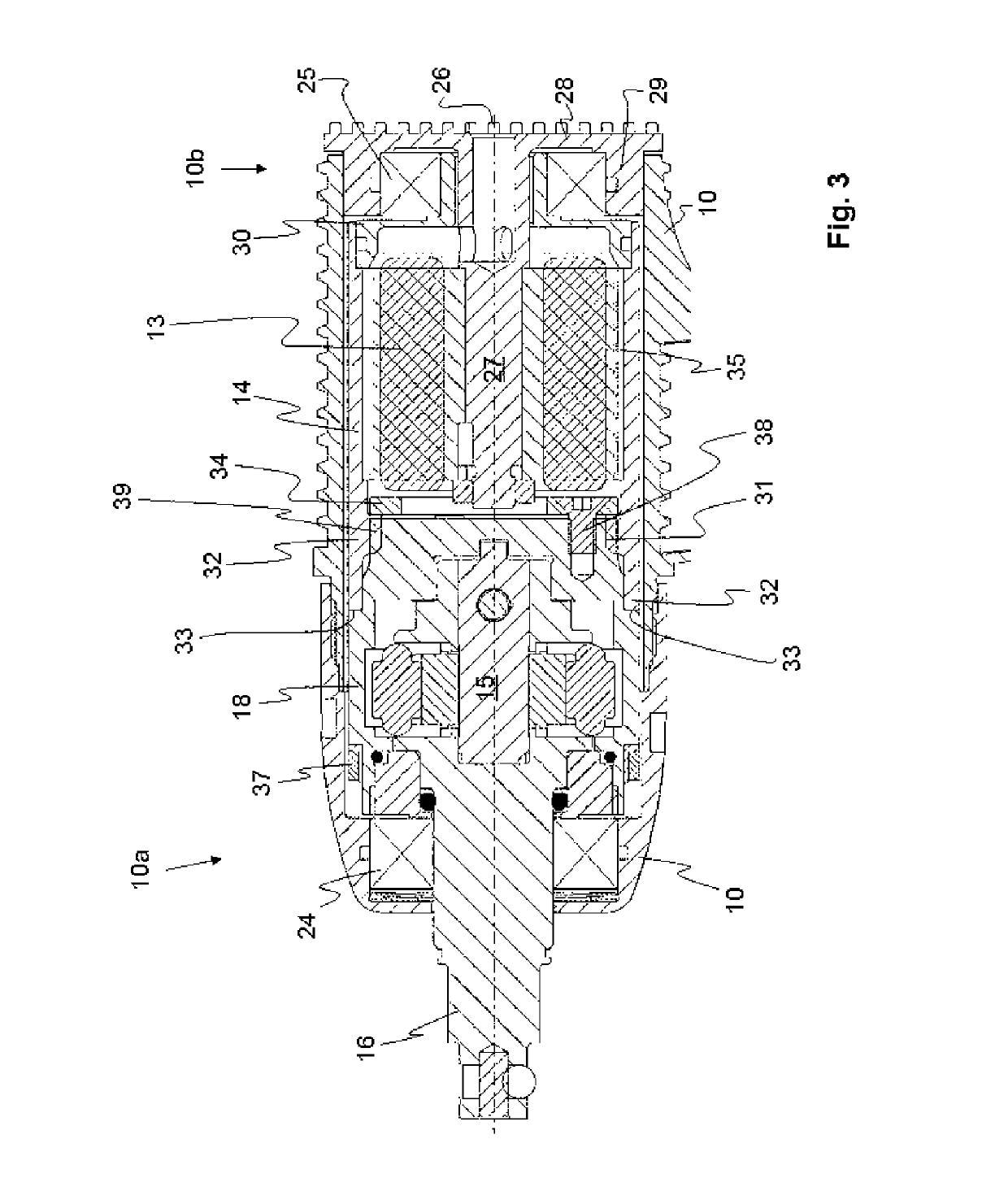
[0033]In order to prohibit mutual movement in the opposite axial direction, i.e. in the separating direction, a block 34 in the form of a solid plate has been provided. The block 34 restricts the movement of the splined coupling part 32 of the rotor 14 away from the splined coupling part 39 of the inertia drive member 18. The block 34 is fastened to a solid portion of the inertia drive member 18 by means of at least three screws 38. This arrangement provides a very solid connection between the rotor 14 and the inertia drive member 18 in both the axial and the radial direction. No central bearing, arranged around the connection of the rotor 14 and the inertia drive member 18, is arranged in this
[0034]In the second embodiment a front bearing 24 is arranged on the output shaft 16, in the same manner as in the first embodiment. Likewise, the front bearing 24 stabilises the output shaft 16 in both the axial and radial direction. In addition it stabilises the inertia drive member 18 in th...
PUM
 Abstract
Description
Claims
Application Information
 - R&D
- Intellectual Property
- Life Sciences
- Materials
- Tech Scout
- Unparalleled Data Quality
- Higher Quality Content
- 60% Fewer Hallucinations
Browse by: Latest US Patents, China's latest patents, Technical Efficacy Thesaurus, Application Domain, Technology Topic, Popular Technical Reports.
© 2025 PatSnap. All rights reserved.Legal|Privacy policy|Modern Slavery Act Transparency Statement|Sitemap|About US| Contact US: help@patsnap.com


