Whole angle MEMS gyroscope on hexagonal crystal substrate

a crystal substrate and gyroscope technology, applied in the direction of speed measurement using gyroscopic effects, instruments, surveying and navigation, etc., can solve the problems of limited rate mode operated gyroscopes, limited coriolis-induced motion measurements, and inability to “keep up” with the movement of the gyroscope. , to achieve the effect of high dynamic range, low damping, and high sensitivity

Active Publication Date: 2019-06-11
THE UNITED STATES OF AMERICA AS REPRESENTED BY THE SECRETARY OF THE NAVY +1
View PDF7 Cites 8 Cited by
  • Summary
  • Abstract
  • Description
  • Claims
  • Application Information

AI Technical Summary

Benefits of technology

[0012]A new MEMS based gyroscope design is provided that combines the best features of a lumped-element TF gyroscope and a rotationally symmetric gyroscope. Certain embodiments efficiently use relatively large masses (e.g., like a TF gyroscope) supported by relatively weak flexures to provide low damping and hence high sensitivity while maintaining an eight-fold symmetry conducive to the n=2 vibratory mode used in most whole angle based gyroscopes to provide high dynamic range. As discussed in more detail below, certain embodiments are capable of operating in both rate and whole angle mode, are low cost, and are easily fabricated.
[0018]According to one embodiment, the gyroscope further comprises a plurality of outside anchors, a plurality of outside shuttles, each located at a periphery of a corresponding one of the plurality of masses, and a plurality of outside flexures, wherein each mass of the plurality of masses is suspended between the central anchor and the plurality of outside anchors via the plurality of internal flexures and the plurality of outside flexures, and wherein each one of the plurality of outside shuttles is configured to restrict rotation of its corresponding one of the plurality of masses. In one embodiment, each one of the plurality of outside shuttles is further configured to decouple x- and y-motion of its corresponding one of the plurality of masses. In another embodiment, each one of the plurality of outside shuttles is further configured to prevent force from being applied circumferentially to its corresponding one of the plurality of masses.

Problems solved by technology

Rate mode operated gyroscopes are limited in that the Coriolis-induced motion measurements are limited by the dynamic range of the open-loop sense axis.
For fast movements of the gyroscope, the open-loop sense axis may not be able to “keep up” with the movement of the gyroscope.
In addition, spring non-linearities at high rates of rotation may cause errors.
However, such gyroscopes are limited by the closed sense loop bandwidth and the maximum force capable of being exerted by the rebalance.
If the frequencies differ substantially, a Coriolis force caused by rotation of the gyroscope will not be sufficient to transfer energy from one mode to the other and the vibration will stay “locked” to a single axis.
This will interfere with the free transfer of motion between modes and the free precession of the mode shape of the gyroscope.
This is because low overall damping correlates to low damping differences between the two axes and on-axis damping may result in gyroscope bias when drive forcers are misaligned.
A mismatch (or mismatch drift) may result in a bias (or bias drift).
An HRG is typically reliable and accurate; however, they are also typically large and costly.
The performance of such ring gyroscopes is limited in that due to the limited mass of the rings, the sensitivity of the gyroscope is relatively low and the bias instability is relatively high.

Method used


Image

  • Whole angle MEMS gyroscope on hexagonal crystal substrate
  • Whole angle MEMS gyroscope on hexagonal crystal substrate
  • Whole angle MEMS gyroscope on hexagonal crystal substrate

Examples


Embodiment Construction

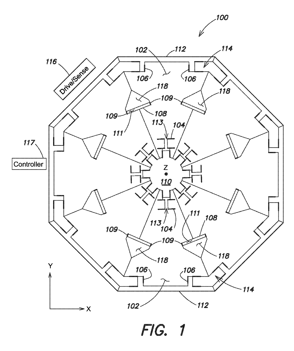
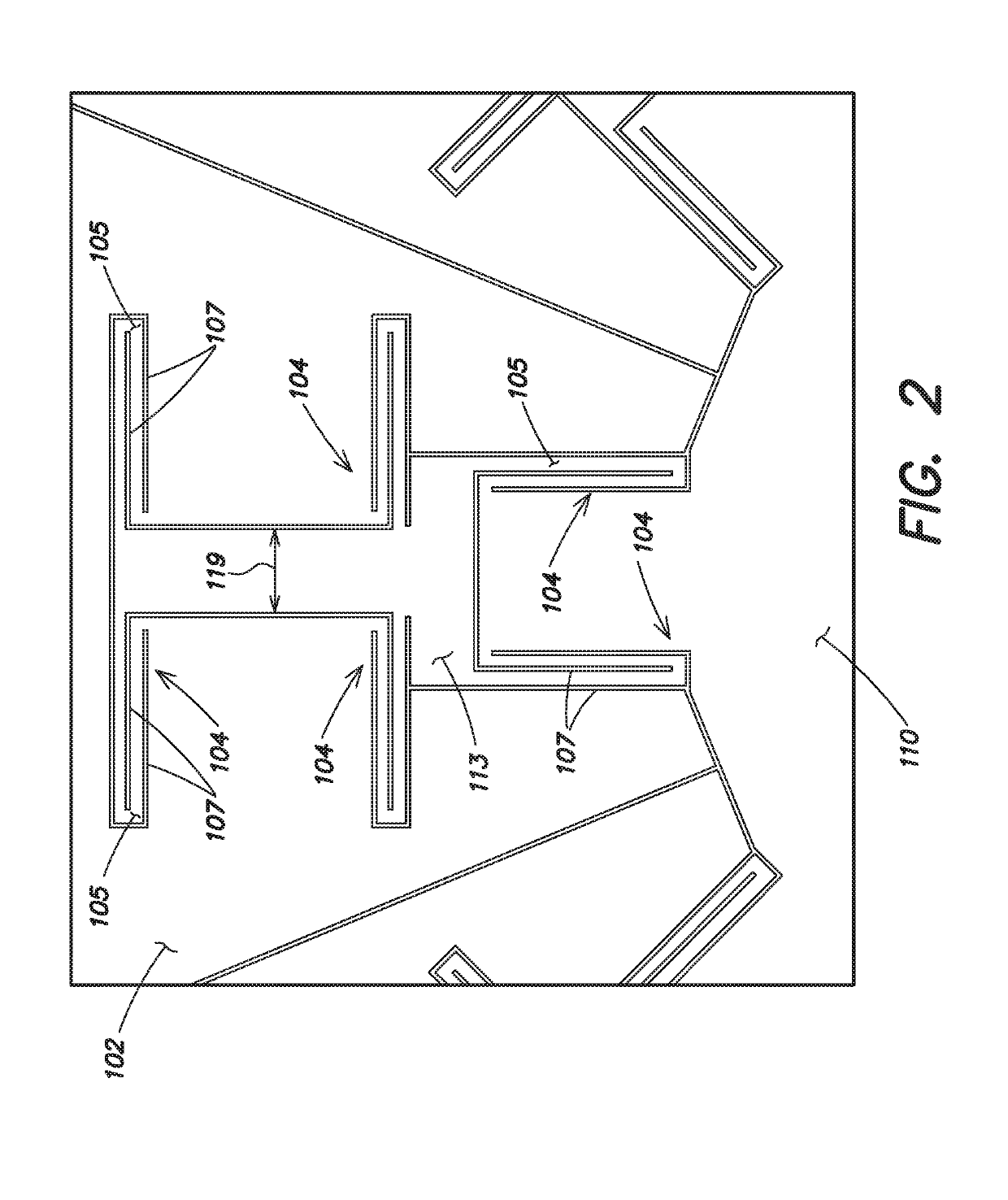
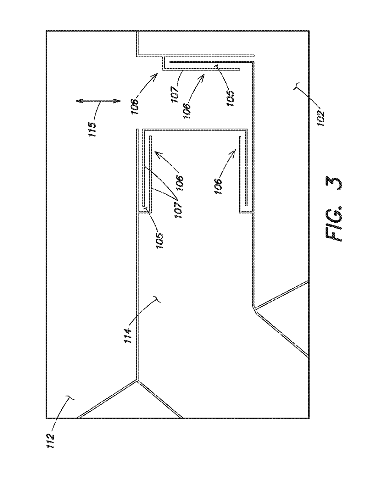
[0059]Aspects and embodiments described herein provide a MEMS based gyroscope design that combines the best features of a TF gyroscope and a rotationally symmetric gyroscope. Certain embodiments efficiently use relatively large masses (e.g., similar to a TF gyroscope) to provide high sensitivity while maintaining an eight-fold symmetry conducive to the n=2 vibratory mode used in most whole angle based gyroscopes to provide high dynamic range. Certain embodiments are capable of operating in both rate and whole angle mode, may be low cost, and may be easily fabricated.

[0060]It is to be appreciated that embodiments of the methods and apparatuses discussed herein are not limited in application to the details of construction and the arrangement of components set forth in the following description or illustrated in the accompanying drawings. The methods and apparatuses are capable of implementation in other embodiments and of being practiced or of being carried out in various ways. Exampl...


PUM


Abstract

According to one aspect, embodiments herein provide a gyroscope comprising an axially symmetric structure, and a plurality of transducers, each configured to perform at least one of driving and sensing motion of the axially symmetric structure, wherein the plurality of transducers is configured to drive the axially symmetric structure in at least a first vibratory mode and a second vibratory mode, and wherein the gyroscope is implemented on a hexagonal crystal-based substrate.

Description

CROSS-REFERENCE TO RELATED APPLICATIONS[0001]The presented application claims priority under 35 U.S.C. § 119(e) to U.S. Provisional Application Ser. No. 62 / 302,474, filed on Mar. 2, 2016 entitled WHOLE ANGLE MEMS GYROSCOPE and U.S. Provisional Application Ser. No. 62 / 165,365, filed on May 22, 2015, entitled WHOLE ANGLE MEMS GYROSCOPE, both of which are hereby incorporated herein by reference.GOVERNMENT LICENSE RIGHTS[0002]This invention was made with government support under N66001-16-C-4020 awarded by SPAWAR SYSTEMS CENTER PACIFIC on behalf of DARPA. The government has certain rights in the invention.BACKGROUND OF THE INVENTION[0003]The present disclosure generally relates to vibrating structure gyroscopes and more specifically to Microelectromechanical System (MEMS) based vibrating structure gyroscopes. Vibrating structure gyroscopes utilize solid-state resonators, of different shapes, to measure orientation or rotation rate based on the principle that a vibrating object tends to ...

Claims


Application Information

Patent Timeline
Patent Type & Authority Patents(United States)
IPC IPC(8): G01C19/5684
CPCG01C19/5684
Inventor KUB, FRANCIS J.HOBART, KARL D.IMHOFF, EUGENEMYERS-WARD, RACHAELCOOK, EUGENE H.WEINBERG, MARC S.BERNSTEIN, JONATHAN J.
Owner THE UNITED STATES OF AMERICA AS REPRESENTED BY THE SECRETARY OF THE NAVY
Why Eureka
Try Eureka