Electromagnetic pressure control valve

a technology of electric pressure control valve and control valve, which is applied in the direction of fluid pressure control, gearing control, slide valve, etc., can solve the problems of pressure control valve failure, piston movement damage, and pressure control valve movement that is difficult to achieve, so as to reduce velocity, prevent the pin from lifting off, and simplify the engagement of the clamping element

Inactive Publication Date: 2019-07-16
ECO HLDG 1 GMBH
View PDF22 Cites 2 Cited by
  • Summary
  • Abstract
  • Description
  • Claims
  • Application Information

AI Technical Summary

Benefits of technology

[0005]Thus it is an object of the instant invention to provide an improved electromagnetic pressure control valve which eliminates the recited operational disadvantages.
[0020]Another advantage of the hydraulic end position damping is its effect during pressure increase exclusively. This means put differently that cut off properties of the valve are not influenced. The instant invention also prevents a lift off of the pin in addition to a hard impact of the pin since a movement impulse in both directions is dampened. Effects from dynamic interferences and pressure oscillation super positions are thus effectively eliminated in both directions. Thus, a cause of a failure of the electromagnetic pressure control valve is already prevented from the beginning. However, in case the pin lifts off from the stop a subsequent impact of the pin occurs with a greatly reduced velocity and thus remains without a damaging effect upon the pressure control valve.

Problems solved by technology

The axial movement of the piston changes a volume formed between the pin and the receiving opening which can cause a damping of the piston movement since the volume is at least partially filled with the hydraulic fluid.
However, there are load conditions during operation of the pressure controller or pressure oscillations in the connections which lead to a lift off of the piston from the wall when the magnet is provided with power and the piston is caused to move.
It is a problem that the pin goes through a strong acceleration and impacts the wall.
This in addition to damaging the wall e.g. by fracturing it leads to a breakout of the wall when the wall is inserted into the controller housing and thus leads to a failure of the pressure control valve.

Method used


Image

  • Electromagnetic pressure control valve
  • Electromagnetic pressure control valve
  • Electromagnetic pressure control valve

Examples


Embodiment Construction

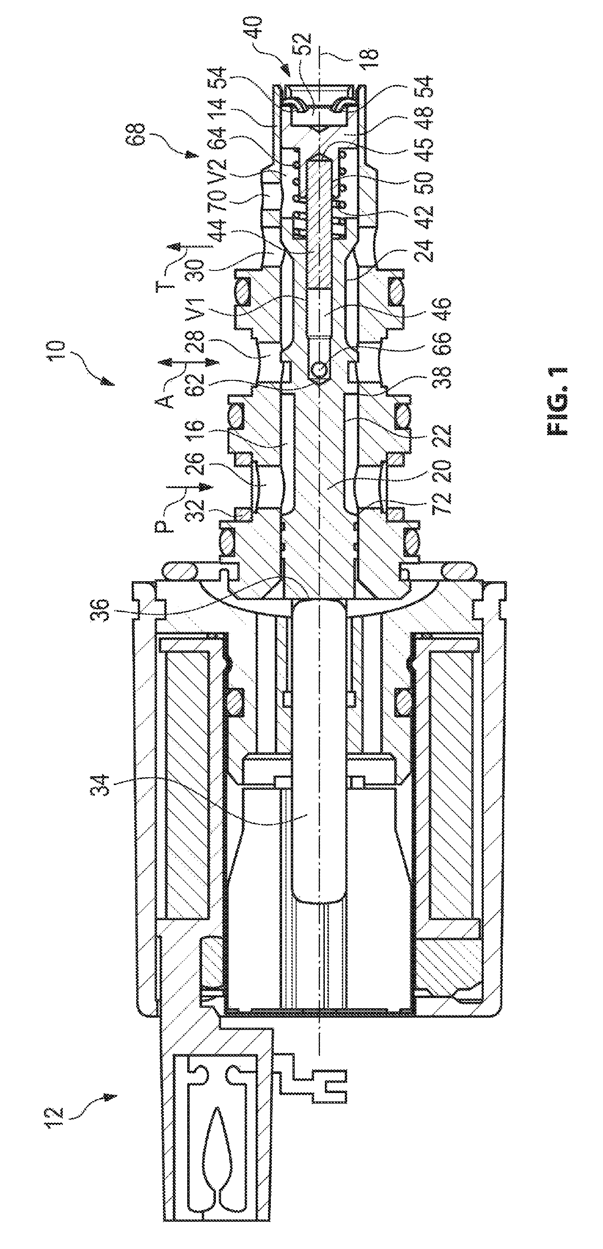
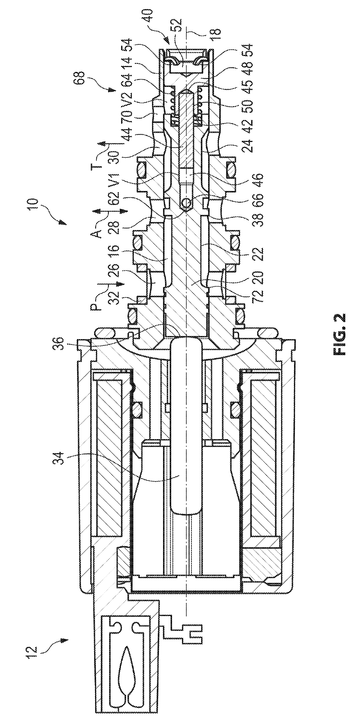
[0026]An electromagnetic pressure control valve 10 according to the invention is configured according to FIG. 1 for a clutch of an automatic transmission of a motor vehicle that is not illustrated in more detail. The pressure control valve 10 is illustrated in FIG. 1 in a first position which is characterized in that the electromagnetic actuator 12 of the pressure control valve 10 is not loaded with electrical current.

[0027]The pressure control valve 10 includes a controller housing 14 which is configured for connecting with hydraulic connections, a supply connection P, a consumer connection A and a tank connection T. In a first receiver opening 16 configured in the controller housing 14 a piston 20 is movably received that is axially movable along a longitudinal axis 18 of the controller housing 14. The controller housing 14 is configured rotation symmetrical with respect to the longitudinal axis 18.

[0028]The piston 20 is configured for controllable flow through of the hydraulic co...


PUM


Abstract

An electromagnetic pressure regulation valve including an electromagnetic actuator that positions a piston that is received axially movable in a controller housing, wherein the piston is configured to open and / or close connections of the pressure control valve for flow through, wherein the piston includes a pin at a face surface that is oriented away from the electromagnetic actuator, wherein a relative movement is facilitated between the pin and the piston, wherein a pin face that is oriented away from the piston in the controller housing is arranged opposite to a stop, wherein the pressure control valve includes a hydraulic end position damping for damping a movement of the pin in a direction towards the stop.

Description

RELATED APPLICATIONS[0001]This application claims priority from and incorporates by reference German Patent Application DE 10 2016 120 118.9 filed on Oct. 21, 2016.FIELD OF THE INVENTION[0002]The invention relates to an electromagnetic pressure control valve according to the preamble of patent claim 1.BACKGROUND OF THE INVENTION[0003]Electromagnetic pressure control valves are known in the art. They are used for example for hydraulically controlling a clutch for an automatic transmission of a motor vehicle. The pressure control valves include an axially movable piston in a controller housing wherein the piston is provided for opening and / or closing connections. The piston is axially moved by an electromagnetic actuator. In order to provide an adaptation of the actuation force of the electromagnetic actuator the pressure control valve includes a pin at a piston end that is oriented away from the electromagnetic actuator wherein the pin is also designated as a needle that is received ...

Claims


Application Information

Patent Timeline
Patent Type & Authority Patents(United States)
IPC IPC(8): F16K31/06G05D16/20F16K3/26F16H61/02F15B13/04
CPCF16K31/0613F15B13/0407G05D16/2013F16K3/26F16K31/0696F16H61/0251F15B13/02
Inventor EISENBERGER, ANDREASFRANZ, BERND
Owner ECO HLDG 1 GMBH
Why Eureka
Try Eureka