Method of video surveillance using cellular communication

a video surveillance and cellular communication technology, applied in the field of video surveillance, can solve the problems of affecting the location of cameras by the limitations of internet accessibility, affecting the ability of ubiquity antennas, and expensive or impossible, and achieve the effect of minimal electrical power

Active Publication Date: 2019-07-16
CALIBER COMM INC
View PDF14 Cites 0 Cited by
  • Summary
  • Abstract
  • Description
  • Claims
  • Application Information

AI Technical Summary

Benefits of technology

[0016]There is a common consensus in the industry that Remote Live Monitoring must be made more intuitive and streamlined then what is currently being offered, particularly to provide a more user friendly environment for end users. These and other needs are addressed by the present invention that provides a repeatable and standardized method of providing remote monitoring systems that require ultra-low power. The invention also addresses the complex environment of remote monitoring and condenses it through automation in order to provide a very easy to use interface that can be configured both locally and remotely.

Problems solved by technology

This has several drawbacks in that multiple software types are required at the central location to monitor multiple sites and consequently monitoring staff must be trained in multiple software types in order effectively control the systems.
Introducing further complications, video surveillance is typically, at least in part, transmitted over large bandwidth wired internet connections which necessitate internet availability at each site where monitoring is to occur.
As such, the camera locations are heavily affected by the limitations of the internet accessibility.
Where internet accessibility is difficult, costly, or impossible the current solution is to use ubiquity antennas.
Inclement weather and blockages to the line of sight can severely impair the ability of Ubiquity antennas to communicate—damaging reliability of the overall system.
Further, having all units communicate with one wired connection introduces the possibility that intermittent internet outages on the single wired connection will cause the entire site to be experience intermittent outages.
Aside from the technical limitation of these systems, the existing systems typically work best for installations which are static and are not moving from one location to the other.
In circumstances where the surveillance area is constantly changing or moving to different sites these static installations become very expensive to install, uninstall, and then reinstall into the new location.
Cellular communication has been used in order to bypass the need for ubiquity antennaes, however, there are limitations in the way information is routed.
As such, this blocking and routing method create limitations on how data can be transmitted over a cellular network, and requires security camera systems that are specifically designed to communicate on cellular networks.
Even where a system works around the limitations of the cellular network, bandwidth throughput is typically throttled such that serving of video streams is limited to shorter clips as opposed to live streaming around the clock.
Cost of Bandwidth limits the ability of a company to monitor a location in real-time (live) due to the inherit bandwidth consumed on a monthly basis in order to monitoring a high-resolution video feed.
If power is not available, implementation may not be possible as current setups typically require larger amounts of power in order to provide effective monitoring.
Further these systems provide minimal redundancy and do not allow end users (clients) any substantial control or input into the monitoring process.

Method used


Image

  • Method of video surveillance using cellular communication
  • Method of video surveillance using cellular communication
  • Method of video surveillance using cellular communication

Examples


Embodiment Construction

[0059]The present concept is schematically represented in FIGS. 1 to 6.

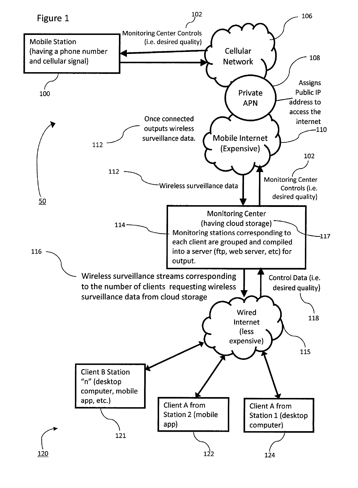
[0060]Referring to FIG. 1 and FIG. 2 which show a methodology for video surveillance using cellular communications referred to generally as 50.

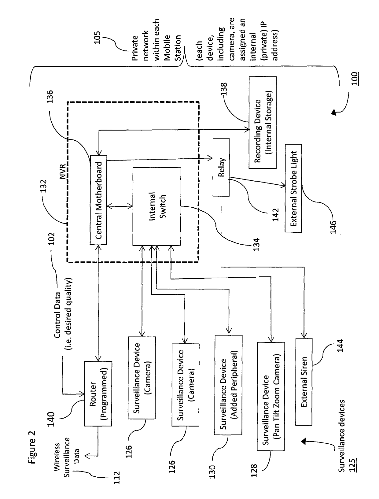
[0061]FIG. 1 shows the flow of data outside a mobile station 100; whereas, FIG. 2 show shows the flow of data inside a mobile station 100.

[0062]The method of video surveillance with a mobile station using cellular communication 50 includes at least one mobile station 100, a cellular network 106, a private APN 108, a monitoring center 114 having cloud storage 117, and client stations shown generally as 120.

[0063]The mobile station 100 includes a programmed router 140 in communication with a private network 105 further comprising: a NVR 132 having an internal switch 134 and a central motherboard 136, surveillance devices 125, a relay 142, a recording device 138, and on-site alert devices—such as, an external strobe light 146 and / or an external siren 144.

[0064]Surveillance de...


PUM


Abstract

A method of video surveillance with a mobile station using cellular communication including the steps of: a) applying power to a mobile station which includes a router in communication with a wireless transceiver for transmitting data wirelessly; b) the router in communication with an private network in the mobile station; c) the private network in communication with surveillance devices attached to the mobile station; d) the router in communication with a private APN via the wireless transceiver over a cellular network and the mobile internet to a monitoring center; and e) the monitoring center receiving wireless surveillance data from the surveillance devices and transmitting control data wirelessly to the devices such that surveillance monitoring and device control is completed wirelessly over a series of networks.

Description

FIELD OF THE INVENTION[0001]The present concept relates to video surveillance and more particularly relates to video surveillance using cellular communication networks.BACKGROUND OF THE INVENTION[0002]Remote monitoring has shown to be a cost effective and capable means of securing physical locations. Current generation remote monitoring is conducted by remotely accessing existing wired camera systems and having the required software in a central location in order to view the cameras based on their communications type.[0003]This has several drawbacks in that multiple software types are required at the central location to monitor multiple sites and consequently monitoring staff must be trained in multiple software types in order effectively control the systems.[0004]Introducing further complications, video surveillance is typically, at least in part, transmitted over large bandwidth wired internet connections which necessitate internet availability at each site where monitoring is to ...

Claims


Application Information

Patent Timeline
Patent Type & Authority Patents(United States)
IPC IPC(8): G06F15/16H04N7/18H04W4/00G08B13/196G08B25/08
CPCH04N7/181H04W4/00G08B25/08G08B13/19667
Inventor VOURKOUTIOTIS, ALEXANDROS JOHN
Owner CALIBER COMM INC
Why Eureka
Try Eureka