
Polymer composite vacuum components

a vacuum component and composite technology, applied in the field of polymer composite vacuum components, can solve the problems of difficult manufacturing of unique geometries, difficult to manufacture housings with nonlinear electrical feedthrough, and high cost of stainless steel, and achieve the effects of low cost, low cost and cost effectiveness

Active Publication Date: 2019-07-23
MKS INSTR INC
View PDF59 Cites 3 Cited by
  • Summary
  • Abstract
  • Description
  • Claims
  • Application Information

AI Technical Summary

Benefits of technology

The patent describes a method of making components of a vacuum gauge using plastic materials. This can decrease manufacturing costs and provide a lighter, smaller, and disposable package. The plastic materials can be used to design and manufacture the typical building blocks of all high vacuum compatible pressure gauges, including leak tight housing, electrical feedthroughs, and mounting flanges. The use of plastics can also reduce assembly errors and cost. The patent also describes a new design for an ionization gauge that uses plastic materials and is compatible with high vacuum levels. Overall, the patent provides a technical solution for making vacuum gauges that are cost-effective, light, and easy to manufacture.

Problems solved by technology

One disadvantage of stainless steel components is that unique geometries are difficult to manufacture due to the limits by which parts can be machined.
It is challenging to manufacture a housing that has nonlinear electrical feedthrough pins with traditional machining processes for metal components.
Additionally, stainless steel can be relatively expensive, thereby increasing the cost of manufacturing for all high vacuum compatible pressure measurement gauges.
Another disadvantage of stainless steel components is the requirement to produce leak tight seals compatible with standard vacuum flanges, which are expensive and very time consuming to implement.
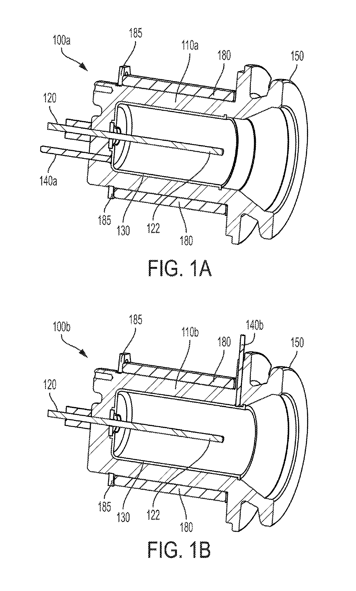
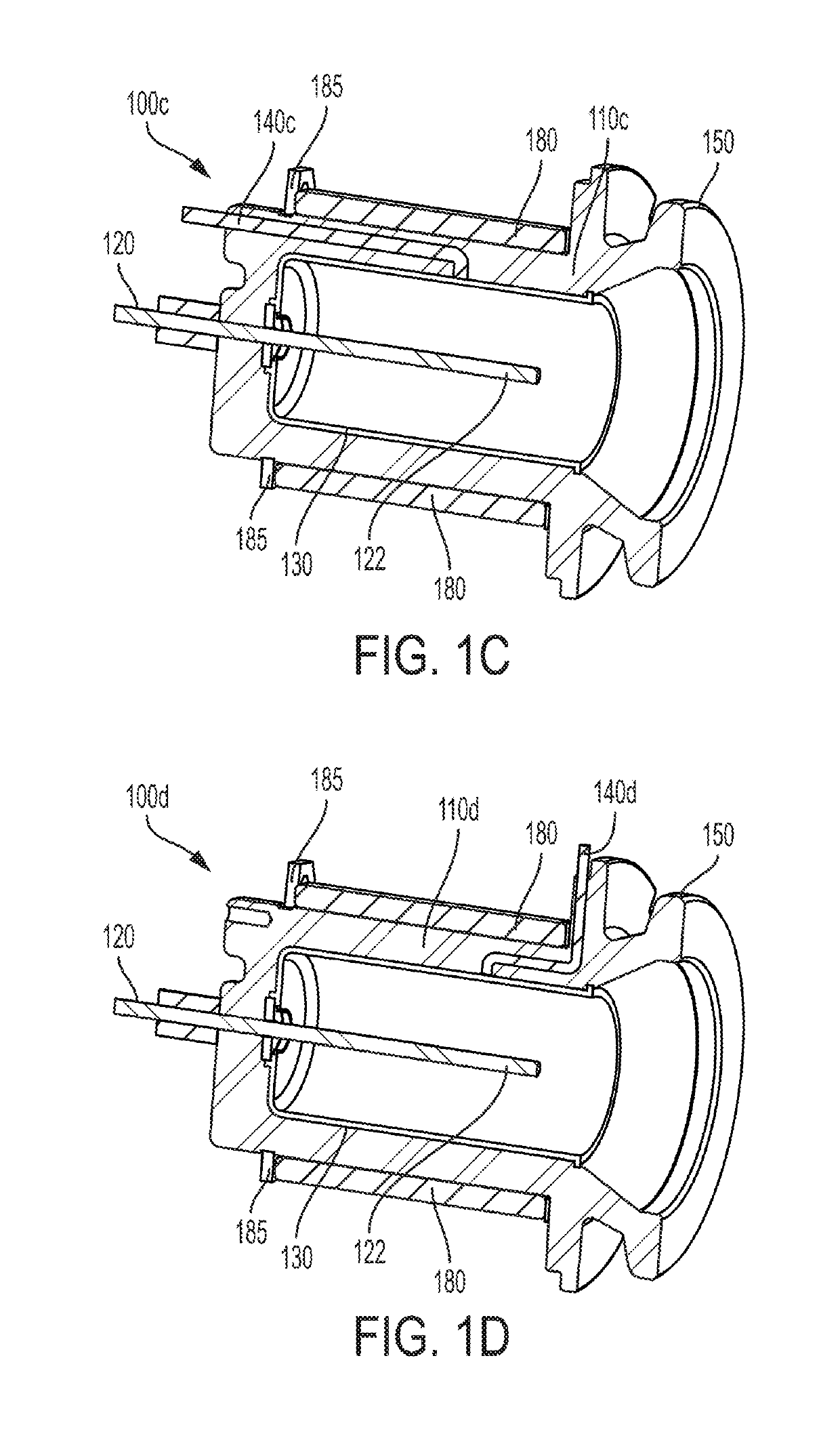
Additionally, a molded housing can have electrical feedthrough pins passing directly through the insulating housing at unique geometries and angles that are difficult to manufacture when the housing is formed of stainless steel or another metal.

Method used


Image

  • Polymer composite vacuum components
  • Polymer composite vacuum components
  • Polymer composite vacuum components

Examples


Embodiment Construction

[0048]A description of example embodiments of the invention follows.

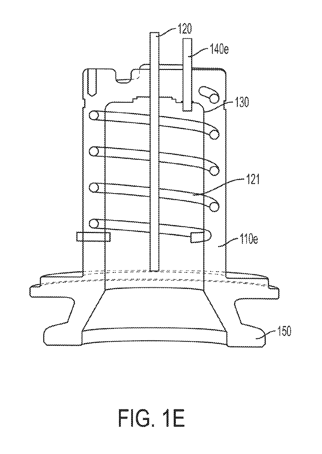
[0049]The cold cathode ionization vacuum gauge described herein relies on the inverted magnetron principle. The gauge is of cylindrical symmetry. A large voltage potential difference (i.e., radial electric field) between the anode pin, located on the axis of the gauge, and the cylindrical cathode, inside the vacuum envelope, provides energy to the electrons for the ionization events to occur. A crossed axial magnetic field provides the longer electron trajectory path length required to sustain a discharge inside the envelope. The discharge current is the measured quantity and is proportional to the total pressure in the system.

[0050]The discharge is established through an avalanche ionization process that generally starts with a single electron being released into the ionization volume of the gauge. The process is responsible for releasing an electron can include a field emission event or a cosmic ray ionization pro...


PUM

PropertyMeasurementUnit
pressuresaaaaaaaaaa
thicknessaaaaaaaaaa
pressuresaaaaaaaaaa

Abstract

A gauge having a housing formed of a polymer material and one or more electrical feedthrough pins disposed in the housing. The electrical feedthrough pins can be oriented substantially perpendicular to each other and have complex shapes.

Description

RELATED APPLICATIONS[0001]This application claims the benefit of U.S. Provisional Application No. 62 / 103,968, filed on Jan. 15, 2015, and U.S. Provisional Application No. 62 / 191,140 filed on Jul. 10, 2015. The entire teachings of the above applications are incorporated herein by reference.BACKGROUND OF THE INVENTION[0002]Accurate and repeatable pressure measurements are an important requirement for the operation of both industrial and research vacuum systems. Pressure gauge sensors used to measure vacuum levels in such applications operate based on a wide range of technological principles and share common building blocks in their design, including: (1) a leak tight envelope that houses the pressure sensing elements, (2) electrical feedthroughs that bridge the envelope walls and exchange power, bias voltages and measurement signals with the electronics and (3) a flange that allows leak tight connection of the gauge sensor to the vacuum system port. Historically, pressure gauge sensor...

Claims


Application Information

Patent Timeline
Patent Type & Authority Patents(United States)
IPC IPC(8): G01L21/34G01L21/30B29C45/14G01L19/00B29K23/00B29K69/00B29K71/00B29L31/00
CPCG01L21/34B29C45/14065G01L19/0084G01L21/30B29L2031/752B29K2023/12B29K2069/00B29K2071/00
Inventor KELLY, BRANDON J.PERCY, CLINTON L.HEINBUCH, SCOTT C.BRUCKER, GERARDO A.SWINNEY, TIMOTHY C.PIWONKA-CORLE, TIMOTHY R.
Owner MKS INSTR INC
Learn More