Automatic power control liquid particle counter with flow and bubble detection systems

a technology of automatic control and liquid particle counter, which is applied in the direction of liquid/fluent solid measurement, instruments, gas dispersion analysis, etc., can solve the problems of overheating, damage to the internal components of the liquid particle counter, damage to the collection and detection system of the particle counter, etc., to prolong the expected lifetime, improve the data quality, and enhance the effect of accuracy

Active Publication Date: 2019-08-06
PARTICLE MEASURING SYST
View PDF34 Cites 22 Cited by
  • Summary
  • Abstract
  • Description
  • Claims
  • Application Information

AI Technical Summary

Benefits of technology

[0008]The systems and methods provided herein relate generally to the improvement of data quality in optical liquid particle counters and control of optical particle counters to achieve longer expected lifetime, for example by avoiding damage caused by electromagnetic radiation and heat. The systems and methods incorporate sensors which characterize the fluid flowing through the flow cell, thereby enhancing accuracy and reducing the number of false positives. The systems and methods detect conditions which may damage components of the particle counter and prevent or minimize potential damage to the system by reducing or eliminating the amount of electromagnetic radiation entering the flow cell or the detection system of the particle counter. Further provided herein, are methods and systems for reducing the amount and size of bubbles prior to entering the flow chamber of a liquid particle counter. The systems and methods are versatile and may be used with a variety of sensors for detecting bubbles or flow rate, including sensors positioned upstream or downstream from the detection zone. In embodiments, for example, the optical particle counter alters the amount of power provided to the optical source upon detection of a change in flow rate or the presence of bubbles. In an embodiment, for example, the particle counter reduces the amount of electromagnetic energy supplied to the flow chamber, for example, by reflecting, refracting, diffusing or blocking the beam of electromagnetic radiation, either from entering the flow chamber or from reaching the collection or detection systems. In embodiments, data recorded during a period of changed flow rate or bubbles is flagged, disregarded or modified.

Problems solved by technology

An issue with modern liquid particle counters is damage to internal components of the liquid particle counter, such as the detector array or the optical source, caused by changes in flow rates or bubbles in the flow chamber of the particle counter, especially in systems that utilize a high powered optical source in order to detect smaller particles.
For example, when bubbles, which may be orders of magnitude larger than the particles of interest, pass through the flow chamber they scatter a large amount of electromagnetic radiation which can overload and damage the collection and detection systems of the particle counter.
Additionally, if the flow rate of the liquid through the flow chamber of the particle counter is too low or stopped, the optical source may boil the liquid which scatters intense radiation throughout the particle viewing flow chamber and into the optical system, damaging the collection and detection systems and / or overheating and damaging the optical source itself.
Bubbles and changes in flow rate through the liquid particle counter also cause data integrity issues.
For example, presently available optical liquid particle counters cannot distinguish between a bubble and a solid particle as they both obscure, scatter or emit electromagnetic radiation.
Therefore, as bubbles pass through the flow chamber of a liquid particle counter they are falsely counted as solid particles, artificially raising the reported contamination of the system being analyzed.
Thus, a non-optimized or non-normal flow rate can cause the particle counter to mischaracterize the particles, for example, by miscounting or mischaracterizing the size of the particles.

Method used


Image

  • Automatic power control liquid particle counter with flow and bubble detection systems
  • Automatic power control liquid particle counter with flow and bubble detection systems
  • Automatic power control liquid particle counter with flow and bubble detection systems

Examples


example 1

itoring System with Optical Source Power Reduction and Data Adjustment

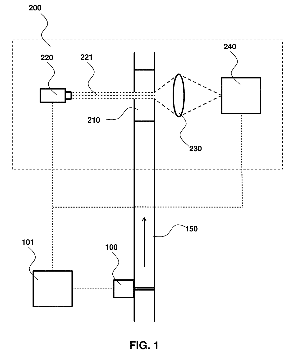
[0055]Certain conventional liquid particle counters are susceptible to problems arising from changes in flow rate and / or the presence of bubbles in the liquid being analyzed. In some circumstances, for instance, optical scattering from bubbles may be indistinguishable from that arising from solid particles and are, thus, counted as contaminants resulting in false positive counts. Further, in high power particle counters, bubbles may refract a large amount of radiation, thereby causing significant scattering or redirection of the beam, resulting in damage to internal components, including the source (e.g. laser) itself. Changes in flow rates may cause similar problems, as low flow rates are susceptible to conditions wherein the fluid sample may undergo an undesired phase change (e.g. boiling) in the flow cell, thus creating bubbles, or overheating and thermally damaging components of the particle counter. Sampling ...

example 2

itoring System with Optical Source Interruption and Data Adjustment

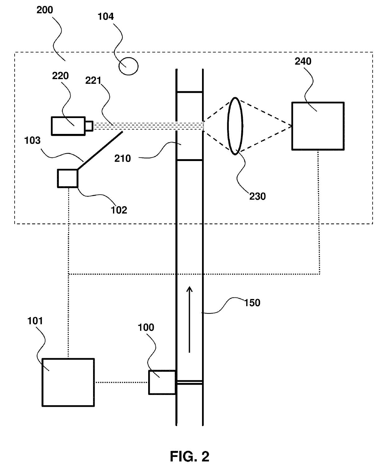
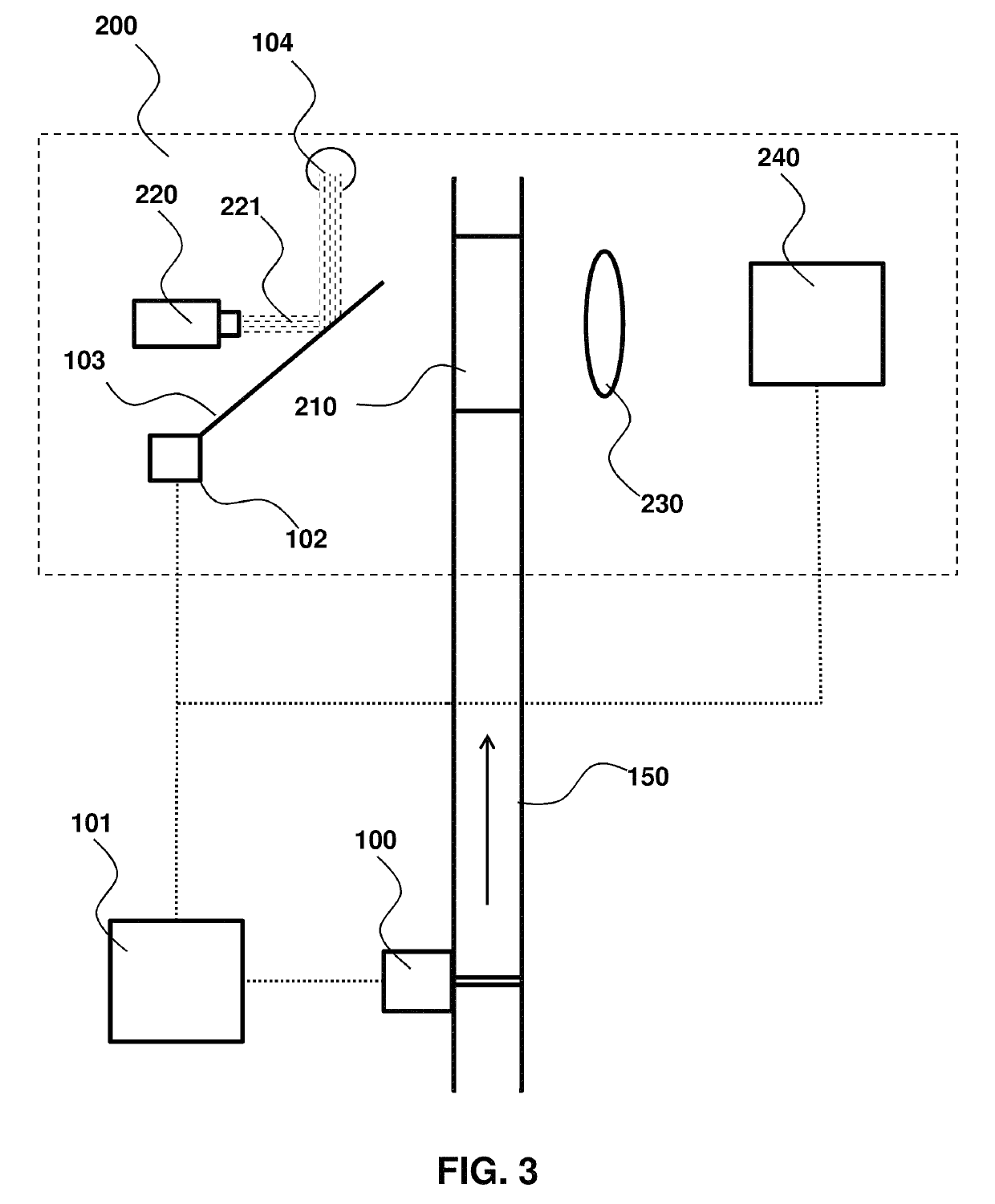
[0065]Another solution to the safety and data integrity issues in optical liquid particle counters caused by bubbles or changes in flow rate (e.g. damage to components, data integrity issues) may be achieved by interrupting or otherwise modulating the optical source, thereby minimizing degradation or damage of the collection and detection systems upon conditions corresponding to bubbles and / or a change in flow rate.

[0066]An example of an interrupting fluid monitoring system is described in FIGS. 2 and 3. The concepts and embodiments described herein, however, are also applicable to other types of particles counters including scattered light or emitted light particle counters as illustrated in FIG. 6.

[0067]In an embodiment, when the fluid monitoring system 100 detects either a bubble or a change in flow rate, including a flow stoppage, it provides a signal(s) to the processor 101. As shown in FIG. 6, the processor 101...

example 3

ditioner

[0069]In addition to the protective measures and optimizing the analysis of particle counter data on the basis of the detection of bubbles and changes in flow rate, it is also advantageous in some embodiments to control and / or reduce the amount of bubbles that may enter the system. Bubbles entering the flow chamber may be controlled, for example, by including a liquid conditioner upstream from the particle counter, to reduce the number or size of bubbles in the fluid being analyzed. In an embodiment, for example, the liquid conditioner may split the liquid stream being analyzed into two separate streams, with one stream having a larger concentration of bubbles.

[0070]FIG. 4 provides a schematic of a system utilizing a liquid conditioner and FIG. 5 shows an exemplary liquid conditioning device. In FIG. 4, the liquid stream 50 being analyzed is split into two separate streams, a bypass stream 51 and a sample stream 52 after passing through the liquid conditioner 110. The liquid...


PUM

PropertyMeasurementUnit
flow rateaaaaaaaaaa
flow rateaaaaaaaaaa
flow rateaaaaaaaaaa

Abstract

The systems and methods provided herein relate generally to the improvement of data quality in optical liquid particle counters and control of optical particle counters to achieve longer expected lifetime, for example by avoiding damage caused by electromagnetic radiation and heat. The systems and methods incorporate sensors which characterize the fluid flowing through the flow cell, thereby enhancing accuracy and reducing the number of false positives.

Description

CROSS-REFERENCE TO RELATED APPLICATIONS[0001]This application claims priority to and the benefit of U.S. Provisional Patent Application No. 62 / 339,694 filed May 20, 2016, which is hereby incorporated by reference in its entirety to the extent not inconsistent herewith.BACKGROUND OF INVENTION[0002]This invention is in the field of optical liquid particle analyzers. In an embodiment, this invention relates generally to systems and methods for improving data quality and protecting optical components, such as a laser, photodetector, or optical lens elements from damage caused by over-heating. In an embodiment, this invention also relates generally to methods and systems for adjusting optical source intensity and acquisition of data during periods in which bubbles are present in the particle analyzer and / or periods in which the fluid is either not flowing or flowing at an optimal rate.[0003]A large portion of the micro-contamination industry and clean manufacturing industries is reliant ...

Claims


Application Information

Patent Timeline
Patent Type & Authority Patents(United States)
IPC IPC(8): G01N15/14G01F1/704G01N15/06G01N15/02G01N15/00H05B37/02
CPCG01N15/1425G01F1/704G01N15/0205G01N15/06G01N15/1459H05B37/0227G01N2015/0011G01N2015/0693G01N2015/1486H05B47/115Y02B20/40G01N21/49G01N21/53H05B47/105
Inventor KNOLLENBERG, BRIANLUMPKIN, JIMHALEY, BRETTSOAPPMAN, MATTRODIER, DANLILLY, MARK
Owner PARTICLE MEASURING SYST
Why Eureka
Try Eureka