Techniques for percutaneous mitral valve replacement and sealing

a technology of mitral valve and percutaneous mitral valve, which is applied in the field of prosthetic valves, can solve the problems of decreased cardiac output and increased total stroke volume, and achieve the effects of facilitating radial facilitating the expansion and facilitating the compression of the prosthetic valv

Active Publication Date: 2019-08-13
CARDIOVALVE LTD
View PDF866 Cites 95 Cited by
  • Summary
  • Abstract
  • Description
  • Claims
  • Application Information

AI Technical Summary

Benefits of technology

[0052]the apparatus being configured such that sliding the control filaments in a first direction through the conduit facilitates expansion of the prosthetic valve, and sliding the control filaments in a second direction through the conduit facilitates compression of the prosthetic valve.
[0053]In an application, the apparatus is configured such that sliding the control filaments in the first direction through the conduit facilitates radial expansion of the prosthetic valve away from the core.
[0071]the apparatus being configured such that sliding of the ratchet housing over the coupling lead in the first direction facilitates coupling of the prosthetic valve to the prosthetic valve support.
[0076]a second expandable prosthetic valve component, including a crimpable frame, and configured to be transcatheterally advanceable toward the native valve, placeable in the native valve while the second prosthetic valve component is in a crimped state thereof, and couplable to the first prosthetic valve component, expansion of the second prosthetic valve component facilitating coupling of the second prosthetic valve component to the first prosthetic valve component; and

Problems solved by technology

Regurgitation of blood from the ventricle into the atrium results in increased total stroke volume and decreased cardiac output, and ultimate weakening of the ventricle secondary to a volume overload and a pressure overload of the atrium.

Method used


Image

  • Techniques for percutaneous mitral valve replacement and sealing
  • Techniques for percutaneous mitral valve replacement and sealing
  • Techniques for percutaneous mitral valve replacement and sealing

Examples


Embodiment Construction

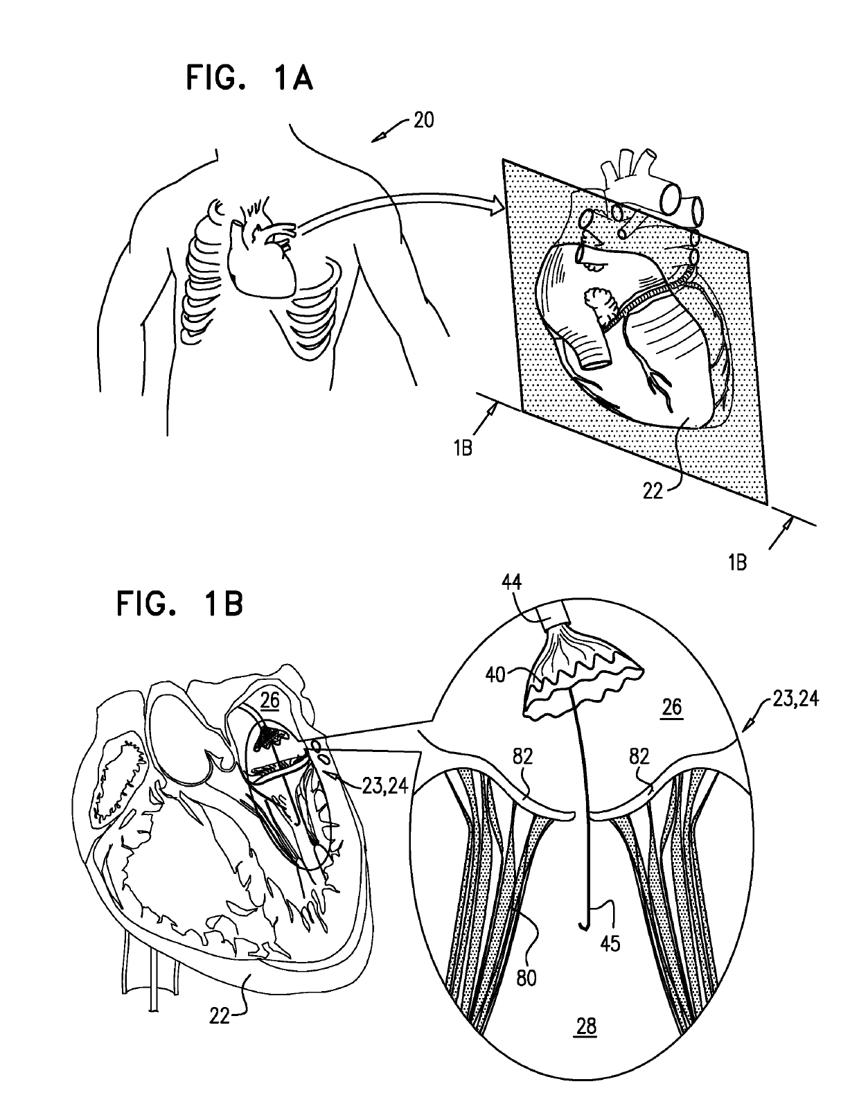
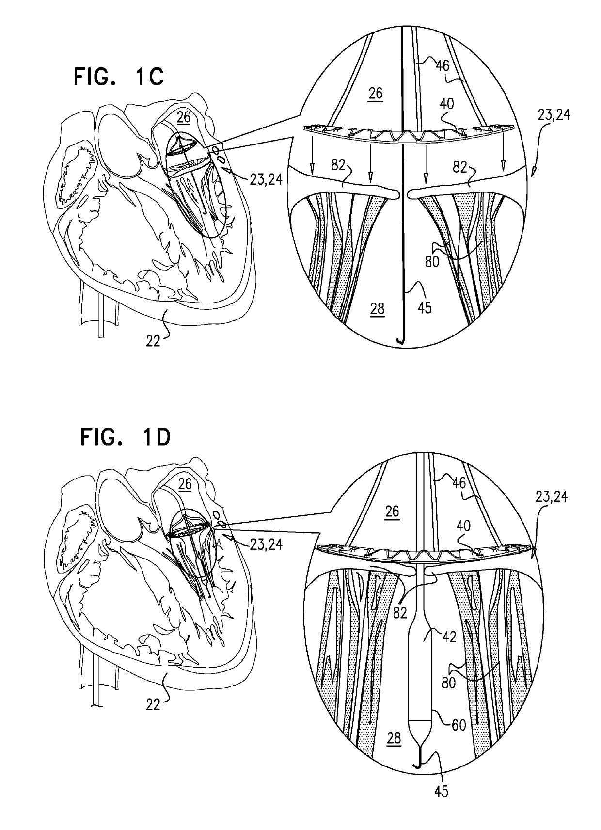
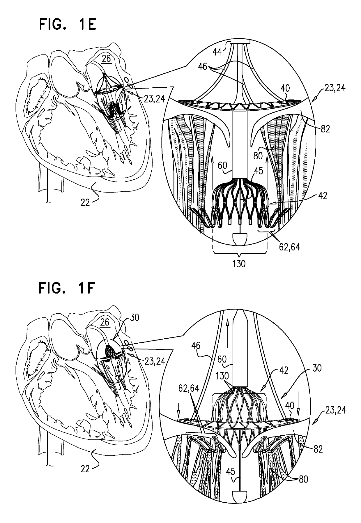
[0160]Reference is made to FIG. 1A-H, which are schematic illustrations of sequential steps in the implantation in a native heart valve 23 of the heart 22 of a subject 20 of an implant 30, comprising (1) a first prosthetic valve component, i.e., prosthetic valve support 40, and (2) a second prosthetic valve component, i.e., a prosthetic valve 42, in accordance with some applications of the present invention. For such applications of the present invention, native valve 23 includes a native mitral valve 24 by way of illustration and not limitation; the scope of the present invention includes implanting implant 30 in other valves of the heart (e.g., the tricuspid valve, the pulmonary valve, or the aortic valve). FIG. 1A illustrates a cross-section through heart 22 of the subject which is used throughout FIG. 1B-G to illustrate the implantation procedure. As shown in the cross-sectional illustration, native mitral valve 24 includes native leaflets 82, which are supported by native chord...


PUM


Abstract

Apparatus is provided for use with a native valve of a heart of a subject. The apparatus includes: (1) an annular upstream support portion, comprising an expandable first frame, the upstream support portion configured to be placed against an upstream surface of the native valve; (2) a flexible polyester connector; and (3) an anchoring element, flexibly coupled to the upstream support portion by the connector, and configured to anchor the upstream support portion to the native valve by engaging tissue of the native valve.

Description

CROSS-REFERENCES TO RELATED APPLICATIONS[0001]This application is a Continuation of U.S. Ser. No. 15 / 213,791 to Gross et al., filed Jul. 19, 2016, which published as US 2016 / 0324633, and which is a Continuation of U.S. Ser. No. 14 / 237,264 to Gross et al., filed May 23, 2014, which published as US 2014 / 0324164, and which is the US National Phase of PCT Application IL2012 / 000292 to Gross et al., filed Aug. 5, 2012, which published as WO 2013 / 021374, and which[0002](1) claims priority from:[0003]U.S. 61 / 515,372 to Gross et al., filed Aug. 5, 2011;[0004]U.S. 61 / 525,281 to Gross et al., filed Aug. 19, 2011;[0005]U.S. 61 / 537,276 to Gross et al., filed Sep. 21, 2011;[0006]U.S. 61 / 555,160 to Gross et al., filed Nov. 3, 2011;[0007]U.S. 61 / 588,892 to Gross et al., filed Jan. 20, 2012; and[0008]U.S. Ser. No. 13 / 412,814 to Gross et al., filed Mar. 6, 2012, (now U.S. Pat. No. 8,852,272) all of which are incorporated herein by reference; and[0009](2) is a Continuation-In-Part of U.S. Ser. No. 13 / ...

Claims


Application Information

Patent Timeline
Patent Type & Authority Patents(United States)
IPC IPC(8): A61F2/24A61F2/848
CPCA61F2/2418A61F2/2436A61F2/2439A61F2/2409A61F2250/0071A61F2/2433A61F2/2442A61F2/848A61F2220/0016A61F2220/0025A61F2220/0091A61F2230/005A61F2230/0013A61F2230/0054A61F2230/0078A61F2250/006A61F2250/0015A61F2250/0069A61F2/2412A61F2/246A61F2220/0008
Inventor GROSSHACOHEN, GILMILLER, ERANZIPORY, YUVAL
Owner CARDIOVALVE LTD
Why Eureka
Try Eureka