Airfoils for stunt flights

Active Publication Date: 2019-09-17
NARVAEZ TIJERINA JUAN GERARDO
View PDF13 Cites 0 Cited by
  • Summary
  • Abstract
  • Description
  • Claims
  • Application Information

AI Technical Summary

Benefits of technology

The airplanes' wings need to be designed to perform well during takeoff and landing, as well as at high speeds with the ability to spin or fly in different directions. This is the purpose of this patent.

Problems solved by technology

Said airfoil's characteristics are not sensitive to surface roughness on the leading edge caused by the accumulation of foreign matter on the airfoil due to the transition to turbulent flow occurring near the leading edge at high lift coefficients, therefore limiting effective use of the airfoils disclosed in the '164 patent to low speeds.

Method used


Image

  • Airfoils for stunt flights
  • Airfoils for stunt flights
  • Airfoils for stunt flights

Examples


Embodiment Construction

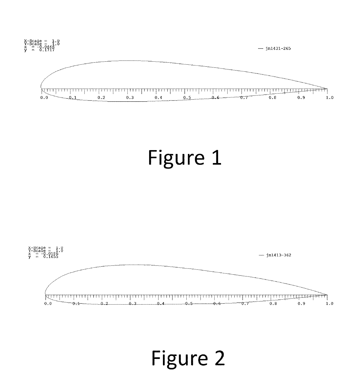
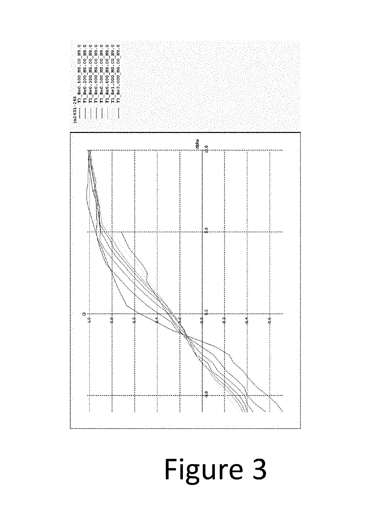
[0010]Airfoils jn1432-265 and jn1413-362, as shown in FIGS. 1 and 2, were designed to be used in the construction of general aviation wings. During the initial phase the design of the upper and lower curves of each airfoil were worked on in order to obtain the highest possible lift coefficient (cl) from is each airfoil section without increasing the camber too much to prevent sacrificing inverted flight, the lift coefficient (cl) differential was also considered between airfoil jn1432-265 and airfoil jn1413-365 in order to have a more predictable stall.

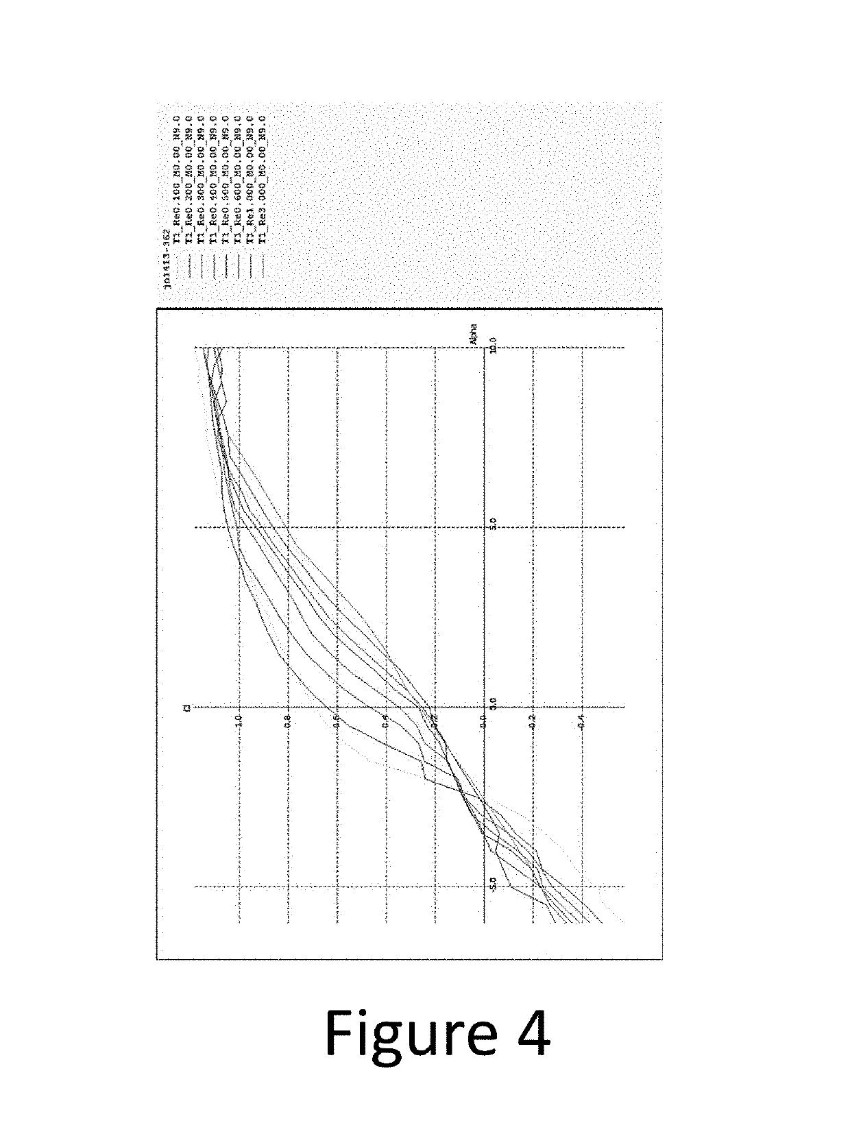
[0011]When analyzing the scale effect we found that the different curves when going through angles between 0 and +1 (taking into account that the angle of incidence in which the wing normally flies is within this range) of the graphs, the lift coefficient is highest when the Reynolds number is lowest and decreases as the Reynolds number increases. As the Reynolds number increases the coefficient adjusts to each flight condition, there...


PUM


Abstract

The invention relates to airfoils, called jn1431-265 and 1413-362, which operate intelligently by adjusting the variable aerodynamics thereof, not only through the attack and sine angle, but also through the effect of scale (air speed), which, when combined, improve the efficiency of the wings configured therewith by up to 30%, cause the wings to experience a predictable stall and also rapidly recover therefrom, and also making the wings configured therewith more efficient at low speed, which reduces the need to use flaps or slats (“high lift devices”), and, in the event that flaps or slats are used, increase the effect of said airfoils even more. On the other hand, at an increased speed, the aerodynamic variables also adjust by up to a third of the value thereof (the angle of attack remaining unchanged), causing the wing to also be very stable at high speed conditions.

Description

PURPOSE OF INVENTION[0001]The purpose is to improve the airfoils' performance for the construction of wings both in their low-speed performance (takeoff and landing) and their stability at high speeds with an acceptable capacity for inverted flight (acrobatic capacity).BACKGROUND[0002]It is well established in the field of aviation and aeronautics that airfoils are developed in accordance with specific purposes of flight (of speed, for gliding, acrobatic, etc.). The objective when designing these airfoils is to have airfoils with an improved flight capacity both at low and at high speeds, and with the capacity for inverted flight. There might be in the state of the technique documents such as the U.S. Pat. No. 6,607,164 B2, which presents an airfoil having particular use in a general aviation aircraft operating at generally low speeds. Said airfoil has a shape designed to produce high lift coefficients at low speeds and low drag and lower lift coefficients at higher speeds. Said air...

Claims


Application Information

Patent Timeline
IPC IPC(8): B64C3/14
CPCB64C3/14Y02T50/12Y02T50/10
Inventor NARVAEZ TIJERINA, JUAN GERARDO
Owner NARVAEZ TIJERINA JUAN GERARDO
Why Eureka
Try Eureka