Pick, in particular a round-shank pick

a pick and round-shank technology, applied in the field of picks, can solve the problems of loss of the tip, failure of the chisel, and reduced wall thickness of the tip, and achieve the effects of promoting the formation of a uniform brazing gap, inexpensive and durable wear-resistant layer, and robust wear-resistant layer

Active Publication Date: 2019-09-17
BETEK
View PDF13 Cites 5 Cited by
  • Summary
  • Abstract
  • Description
  • Claims
  • Application Information

AI Technical Summary

Benefits of technology

[0007]It is, therefore, an object of the present invention to provide a chisel of the type mentioned in the introduction which exhibits an improved mechanical load capacity. It is a further object of the present invention to provide a method for coating a chisel head and a further method for producing a chisel head of this type.
[0008]The object of the present invention relating to the chisel is achieved in that the base part has an axially oriented recess for receiving a fastening section of the cutting element, in that the base part has, encircling the recess, a counterpart face which faces toward the cutting element, and in that the counterpart face and the front face of the wear-resistant layer form a continuous planar face, or in that the front face of the wear-resistant layer extends to the counterpart face. Since the fastening section of the cutting element is held in the recess of the base part, thin-walled sections of the cutting element, which are subjected to intense action of external forces, are avoided. The risk of breakage of the tip is, thus, considerably reduced. The planar face formed by the counterpart face and the front face makes it possible for a uniform brazing gap to be formed between the planar face and the cutting element. It is thus possible to realize an optimized brazed connection between the cutting element and the base part of the chisel, which connection is not severed even under intense mechanical load. By virtue of the fact that the base part has a recess rather than a projection for the connection to the cutting element, the continuous planar face between the counterpart face and the front face of the wear-resistant layer can be produced easily in terms of manufacturing.

Problems solved by technology

In practical use, the axial recess leads to disadvantages, because the wall thickness of the tip is reduced in the region of the axial recess.
The stress peaks increasingly lead, in the case of the relatively small wall thickness of the tip in the region, to fracture of the tip, which is produced from a brittle hard material, and thus to failure of the chisel.
A further disadvantage arises from the possible production method for such an arrangement.
The non-uniform brazing gap leads to an inadequate brazed connection, which can detach during use and lead to loss of the tip.

Method used


Image

  • Pick, in particular a round-shank pick
  • Pick, in particular a round-shank pick
  • Pick, in particular a round-shank pick

Examples


Embodiment Construction

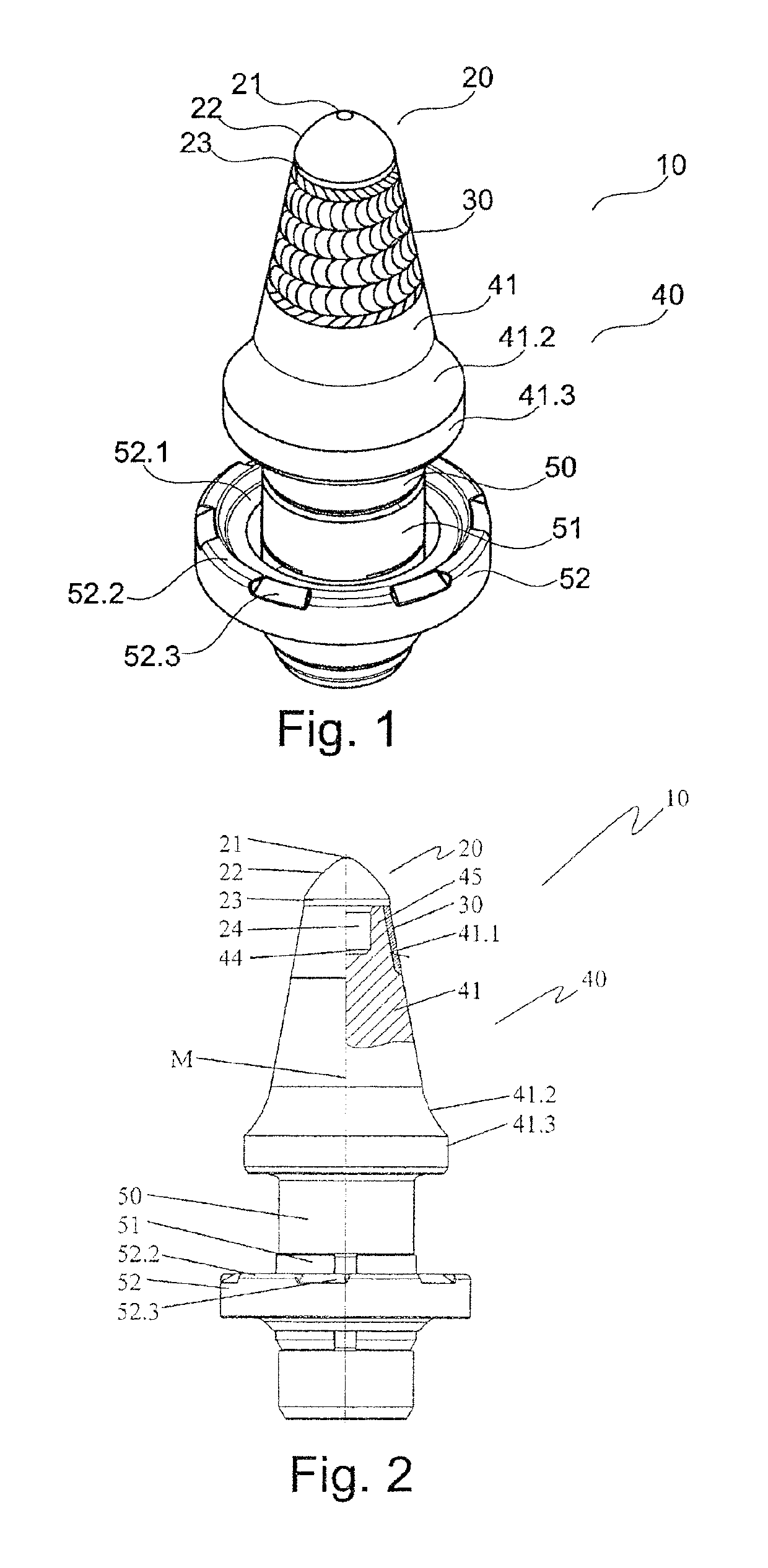
[0040]FIG. 1 shows, in a perspective side view, a chisel 10 having a chisel shank 50 and having a chisel head 40 with a wear-resistant layer 30. The chisel 10 is in the form of a round-shank chisel. The chisel head 40 is assigned a cutting element 20 composed of a hard material, for example, of hard metal. The cutting element 20 is connected, in the present exemplary embodiment by brazing, to a base part 41, which tapers conically toward the cutting element 20, of the chisel head 40. In a region facing toward the cutting element 20, the base part 41 is coated with the wear-resistant layer 30 in an encircling manner around the cutting element 20. The wear-resistant layer 30 is composed of a hard material and is applied to the base part 41 by means of a welding process. In the exemplary embodiment shown, the wear-resistant layer 30 is formed from hard metal. It may also be produced from an iron alloy, from a nickel alloy, from a cobalt alloy, from a titanium alloy, from tungsten carbi...


PUM


Abstract

A round-shank pick, comprising a pick head and a pick shank, the pick head including a base part and a cutting element, which is connected to the base part and is composed of a hard material, in particular hard metal, wherein the base part has a wear-resistant layer on the outer surface thereof at the connection to the cutting element, which wear-resistant layer covers at least one segment of the outer surface of the base part facing the cutting element and wherein an end face of the wear-resistant layer facing the cutting element is covered by the cutting element. The base part has an axially oriented cut-out for receiving a fastening segment of the cutting element, the base part has a counter surface facing the cutting element and extending around the cut-out, and the counter surface and the end face of the wear-resistant layer form a continuous flat surface.

Description

CROSS REFERENCE TO RELATED APPLICATIONS[0001]This application is a continuation of International Application No. PCT / EP2016 / 051342 filed Jan. 22, 2016, which designated the United States, and claims the benefit under 35 USC § 119(a)-(d) of German Application No. 10 2015 101 063.1 filed Jan. 26, 2015, the entireties of which are incorporated herein by reference.FIELD OF THE INVENTION[0002]The present invention relates to a chisel, in particular, a round-shank chisel, having a chisel head and having a chisel shank, wherein the chisel head is formed at least from a base part and from a cutting element which is connected to the base part and which is composed of a hard material, in particular of hard metal, wherein the base part has, adjacent to the cutting element, a wear-resistant layer on its outer face, which wear-resistant layer covers at least one section, facing toward the cutting element, of the outer face of the base part, and wherein a front face, facing toward the cutting ele...

Claims


Application Information

Patent Timeline
Patent Type & Authority Patents(United States)
IPC IPC(8): E21C35/18E21C35/183E21B10/46E21C35/19E21C35/197
CPCE21B10/46E21C35/183E21C35/197E21C2035/1813E21C35/19E21C2035/1806E21C35/1831E21C35/1835
Inventor KRAEMER, ULRICHFRIEDERICHS, HEIKOHABERSTROH, CHRISTOPHALLGAIER, THOMAS
Owner BETEK
Why Eureka
Try Eureka