Emergency lubrication device of simplified architecture for a power transmission main gearbox of an aircraft

a technology of transmission gearbox and emergency lubrication device, which is applied in the direction of engine lubrication, gearboxes, air transport, etc., can solve the problems of limited duration, rapid degradation of mechanical system, and exposure to impacts from birds or indeed ice, so as to improve reliability, simplify the architecture of emergency lubrication device, the effect of reducing weight and cos

Active Publication Date: 2019-09-17
EUROCOPTER
View PDF14 Cites 4 Cited by
  • Summary
  • Abstract
  • Description
  • Claims
  • Application Information

AI Technical Summary

Benefits of technology

[0025]An object of the present invention is thus to propose an emergency lubrication device for a mechanical system that makes it possible to overcome the above-mentioned limitations, enabling essential members of the mechanical system to be lubricated in spite of the presence of a fault in the main lubrication circuit for some guaranteed minimum limited duration. The present invention also seeks to simplify the architecture of the emergency lubrication device in order to improve its reliability, while also reducing its weight and its cost.

Problems solved by technology

Without such lubrication, the operation of the mechanical system can rapidly become degraded, or even impossible.
The cooling circuit outside the mechanical system constitutes a vulnerable portion of a lubrication circuit of the mechanical system when it comes to leaks.
Nevertheless, it can be exposed to impacts against birds or indeed ice, for example.
As a result, one or more leaks may appear in the couplings and the pipes and also in the heat exchanger, which leaks are caused essentially by these vibratory and thermal stresses.
Such leaks generally allow the mechanical system to continue to be lubricated, but for a duration that is limited.
Specifically, it can happen that all of the oil stored in the lubrication circuit, e.g. in a tank, becomes discharged to the outside of the lubrication circuit via such leaks.
Such leaks may possibly be detected by a drop in the pressure of the oil in the lubrication circuit.
In the event of this lubrication being lost, damage can therefore appear rapidly in the operation of the mechanical system.
By way of example, the consequence of such damage taking place in a mechanical system forming part of a motor vehicle, may be the vehicle coming to a stop immediately, or else coming to a stop after the oil in the lubrication circuit has been consumed.
In contrast, if the mechanical system is a power transmission main gearbox of a rotary wing aircraft, such damage to the lubrication circuit of the power transmission main gearbox can then have consequences that are catastrophic, such as an emergency landing or indeed a crash of the aircraft.
Nevertheless, although that emergency circuit enables a mechanical system to be lubricated sufficiently in the event of a failure of the main circuit, it is in fact used only rarely.
As a result, the emergency circuit constitutes an on-board weight that is rarely used.
Furthermore, the zones where leaks appear in the main lubrication circuit are frequently to be found in the heat exchanger and its couplings.
The drawback of the bypass system is that it leaves open the possibility of a dormant (hidden) failure in the emergency circuit, with this failure being detected only at the moment when the emergency circuit is put into operation.
Under such circumstances, this is a major anomaly that might be mission critical on a rotary wing aircraft.
As a result, in the event of a leak from either of the lubrication circuits, the casing of the power transmission main gearbox will sooner or later become empty and lead to a failure of the complete lubrication system.

Method used


Image

  • Emergency lubrication device of simplified architecture for a power transmission main gearbox of an aircraft

Examples


Embodiment Construction

[0093]Elements present in more than one of the figures are given the same references in each of them.

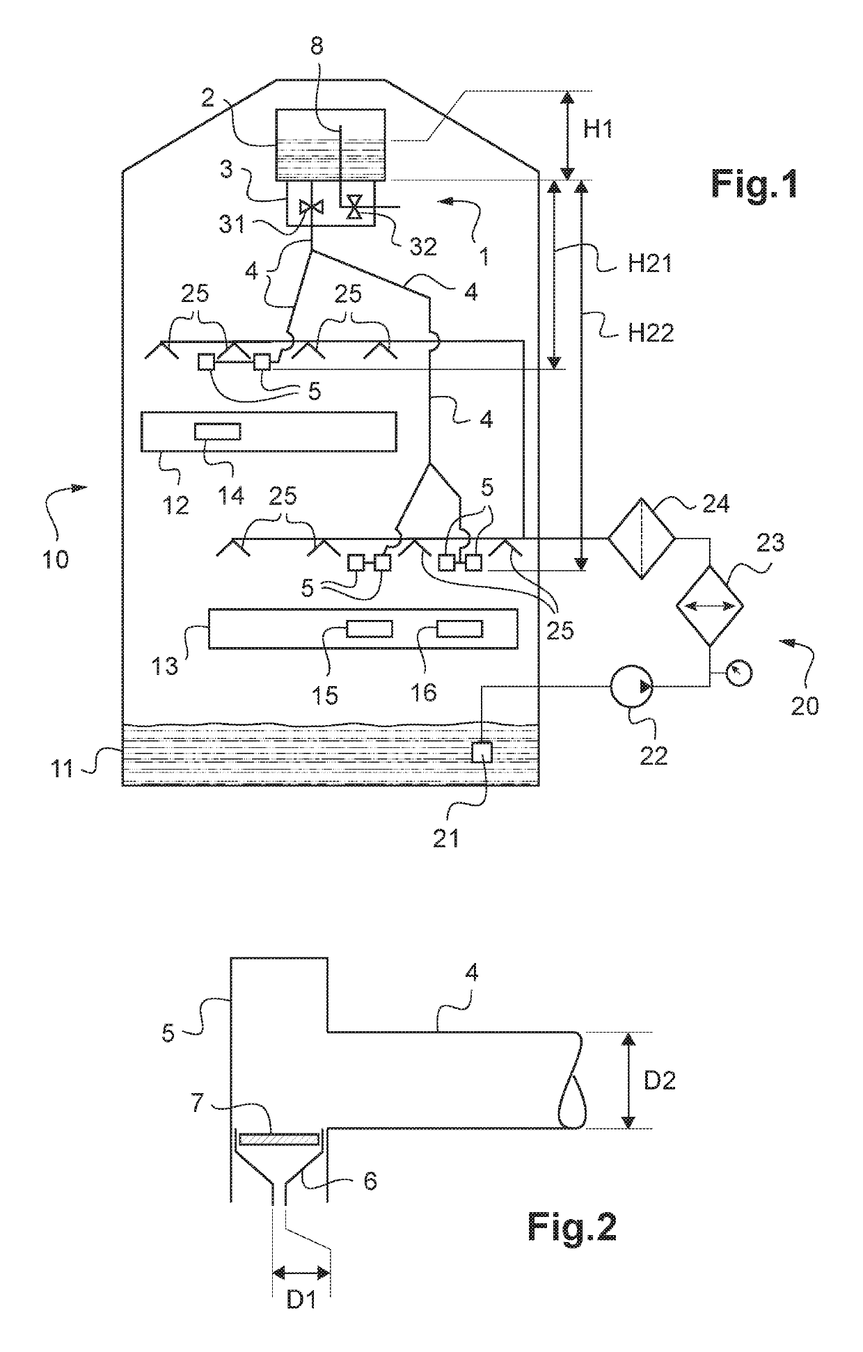
[0094]A mechanical system 10 comprising both main lubrication means 20 and also an emergency lubrication device 1 is shown in FIG. 1. The mechanical system 10 includes in particular rotary elements 12, such as shafts and bearings, and power transmission elements 13 and speed increasing or decreasing elements, such as pinions and / or gears. The mechanical system 10 may for example be a power transmission main gearbox of a rotary wing aircraft.

[0095]The main lubrication means 20 and the emergency lubrication device 1 serve to lubricate and cool some or all of the mechanical elements 12, 13 in the mechanical system 10.

[0096]The main lubrication means 20 include a suction point 21, a pump 22, a heat exchanger 23, a filter 24, and spray nozzles 25. The spray nozzles 25 are positioned above the rotary elements 12 and the transmission elements 13. The pump 22 serves to suck up a lubrication ...


PUM


Abstract

An emergency lubrication device of simplified architecture for a mechanical system. The emergency lubrication device has a tank, trigger means, at least one pipe, and at least one distribution means. The tank contains a lubrication liquid and it is arranged inside the mechanical system and above the pipes and the distribution means. Each distribution means includes at least one constriction means for limiting the flow rate of the lubrication liquid. The lubrication liquid is heated by the mechanical system, and the viscosity of the lubrication liquid decreases so that the flow rate of the lubrication liquid through each distribution means is substantially equal to or greater than a minimum flow rate so long as the tank contains the lubrication liquid.

Description

CROSS REFERENCE TO RELATED APPLICATION[0001]This application claims priority to French patent application No. FR 15 02623 filed on Dec. 17, 2015, the disclosure of which is incorporated in its entirety by reference herein.BACKGROUND OF THE INVENTION[0002](1) Field of the Invention[0003]The present invention relates to the field of emergency lubrication for transmission gearboxes, in particular power transmission main gearboxes for a rotary wing aircraft.[0004]The present invention relates to an emergency lubrication device of simplified architecture for a mechanical system. The emergency lubrication device is particularly adapted to lubricating a power transmission main gearbox of a rotary wing aircraft.[0005](2) Description of Related Art[0006]A mechanical system generally includes rotary elements, such as shafts and bearings, together with power transmission elements and speed increasing or decreasing elements, such as pinions and / or gears. It is then essential for proper operatio...

Claims


Application Information

Patent Timeline
Patent Type & Authority Patents(United States)
IPC IPC(8): F16H57/04F16N39/04F16N29/02F16H57/02F16N21/00F16N25/00F16N7/02F01D25/18F01D25/20
CPCF16N21/00F01D25/18F16H57/0436F16N25/00F01D25/20F16N39/04F16H57/0435F16H57/0442F16H57/045F16N29/02F16H57/0456F16H57/02F16N7/02F16N2260/24F16N2270/56F16N2200/12F05D2260/98F16N2210/08F16N2280/00Y02T50/60
Inventor LAPEYRE, JEAN-VICTOREYMARD-DUVERNAY, GILLES
Owner EUROCOPTER
Why Eureka
Try Eureka