Supercharge Your Innovation With Domain-Expert AI Agents!

Engine device

a technology of engine and hose, which is applied in the direction of machines/engines, mechanical equipment, agricultural tools and machines, etc., can solve the problems of inability to simplify the attaching structure the measurement of an amount of nitrogen oxide becomes improper, and the durability of the urea water supply hose or the electric wiring cannot be improved. , to achieve the effect of improving the durability, excellent in durability, and improving the attaching rigidity

Active Publication Date: 2019-10-08
YANMAR POWER TECHNOLOGY CO LTD
View PDF34 Cites 1 Cited by
  • Summary
  • Abstract
  • Description
  • Claims
  • Application Information

AI Technical Summary

Benefits of technology

The technical effect of this patent is to improve the quakeproofing performance and rigidity of the urea water injection portion in the exhaust gas connection pipe to prevent damage caused by engine oscillation. Additionally, the patent aims to simplify the attachment structure and reduce the need for special installation of the urea water injection portion.

Problems solved by technology

However, in the structure in which the urea water injection portion is installed in the exhaust gas connection pipe, the urea water injection portion tends to be damaged by the oscillation of the engine, so that there is a problem that it is necessary to reduce the oscillation of the urea water injection portion by enhancing a quakeproofing performance of the urea water injection portion or improving a rigidity of the SCR case.
Further, in the structure in which the urea water injection portion is installed in the exhaust gas connection pipe, a urea water supply hose or an electric wiring tends to fall down or be disconnected due to the oscillation of the engine in the case that the urea water supply hose or the electric wiring connected to the urea water injection body is supported to the main machine side, so that there is a problem that it is impossible to improve a durability of the urea water supply hose or the electric wiring and it is impossible to simplify an attaching structure of the urea water supply hose or the electric wiring.
Further, in the case of being provided with an NOx sensor which detects nitrogen oxides included in the exhaust gas within the SCR case, measurement of an amount of nitrogen oxides becomes improper in the structure in which the NOx sensor detects the exhaust gas in an exhaust gas accumulation portion in an exhaust gas outlet of the cylindrical SCR case, and the NOx sensor can not be compactly installed in the structure in which the NOx sensor protrudes out of an outer peripheral surface of the cylindrical SCR case in an outer diameter direction (a radial direction).

Method used


Image

  • Engine device
  • Engine device
  • Engine device

Examples


Embodiment Construction

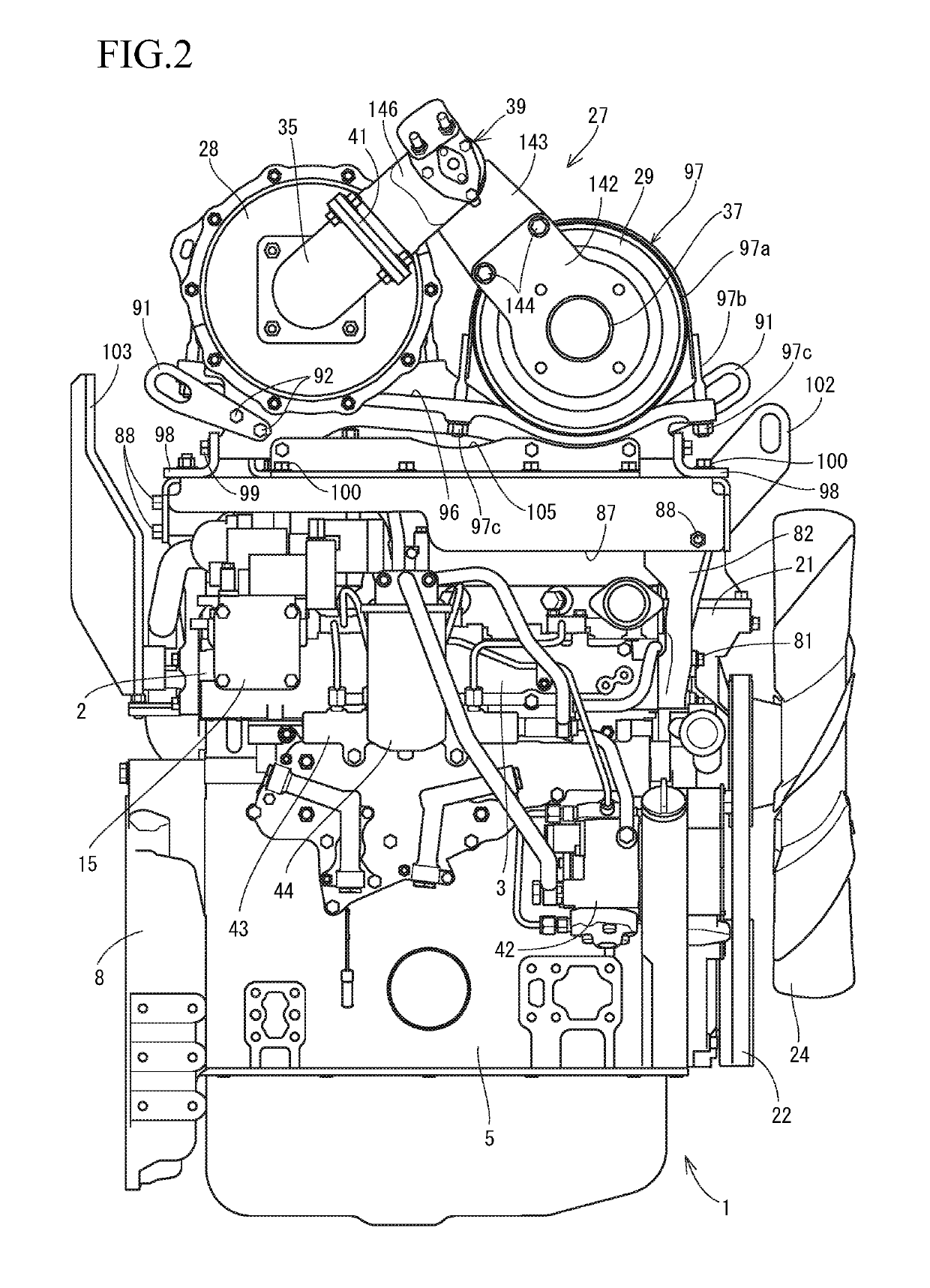
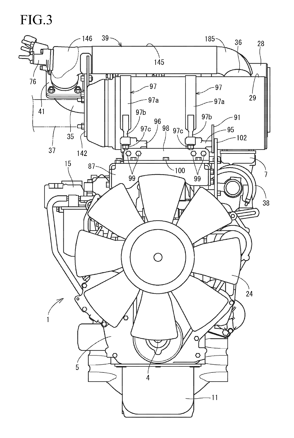
[0057]A description will be given below of a first embodiment obtained by embodying the present invention with reference to the accompanying drawings (FIGS. 1 to 20). FIG. 1 is a left side elevational view of a diesel engine 1 in which an exhaust gas manifold 6 is installed, FIG. 2 is a right side elevational view of the diesel engine 1 in which an intake air manifold 3 is installed, and FIG. 3 is a front elevational view of the diesel engine 1 in which a cooling fan 24 is installed. A side in which the exhaust gas manifold 6 is installed is called as a left side surface of the diesel engine 1, a side in which the intake air manifold 3 is installed is called as a right side surface of the diesel engine 1, and a side in which the cooling fan 24 is installed is called as a front surface of the diesel engine 1.

[0058]A description will be given of a whole structure of the diesel engine 1 with reference to FIGS. 1 to 5. As shown in FIGS. 1 to 5, an intake air manifold 3 is arranged in on...


PUM


Abstract

In an engine device having a urea mixing pipe which injects urea water into exhaust gas of an engine, and an SCR case which removes nitrogen oxides in the exhaust gas of the engine, and structured such that an inlet side of the SCR case is connected to an outlet side of the urea mixing pipe, an exhaust gas outlet side of the SCR case is connected to an exhaust gas inlet side of the urea mixing pipe where a urea water injection means is arranged, and an exhaust gas inlet side of the urea mixing pipe is supported to the exhaust gas outlet side of the SCR case.

Description

CROSS-REFERENCE TO RELATED APPLICATIONS[0001]The present application is a continuation application of International Application No. PCT / JP2015 / 077305, filed Sep. 28, 2015, which claims priority to Japanese Patent Application No. 2014-205767, filed Oct. 6, 2014, Japanese Patent Application No. 2014-205768, filed Oct. 6, 2014 and Japanese Patent Application No. 2014-205769, filed Oct. 6, 2014. The contents of these applications are incorporated herein by reference in their entirety.BACKGROUND OF THE INVENTION[0002]The present invention relates to an engine device.[0003]There has been conventionally known a technique of purifying the exhaust gas discharged from the diesel engine by arranging a case inward provided with a diesel particulate filter (hereinafter, refer to as a DPF case), and a case inward provided with a urea selective reducing type catalyst (hereinafter, refer to as an SCR case), as an exhaust gas purification device (an exhaust gas aftertreatment device) in an exhaust c...

Claims


Application Information

Patent Timeline
Patent Type & Authority Patents(United States)
IPC IPC(8): F01N3/20F01N3/28F01N11/00F01N13/00A01D41/12
CPCF01N11/007A01D41/12F01N3/2066F01N13/008F01N3/2892F01N2590/08Y02T10/24F01N2560/026F01N2610/02F01N2550/05Y02T10/12F01N3/28F01N2610/14
Inventor MATSUI, YUSANDOU, YOSHIYUKI
Owner YANMAR POWER TECHNOLOGY CO LTD
Features
  • R&D
  • Intellectual Property
  • Life Sciences
  • Materials
  • Tech Scout
  • Unparalleled Data Quality
  • Higher Quality Content
  • 60% Fewer Hallucinations
Learn More