
Centrifugal separator with annular piston for solids extrusion

a centrifugal separator and annular piston technology, applied in centrifuges, rotary centrifuges, etc., can solve the problems of reducing the recovery yield of solids, reducing the efficiency of radial-motion scrapers, and other separators not providing a convenient means of handling and recovering sensitive solids, etc., to achieve efficient extrusion of accumulated solids

Inactive Publication Date: 2019-10-22
CARR ROBERT BRET
View PDF26 Cites 2 Cited by
  • Summary
  • Abstract
  • Description
  • Claims
  • Application Information

AI Technical Summary

Benefits of technology

The design enhances solids recovery with reduced contamination and degradation, simplifies maintenance, and improves the efficiency of solids separation by using a central core tube to feed liquid, resulting in dryer solids and clearer centrate.

Problems solved by technology

However, such a radial-motion scraper does not effectively remove wet or sticky solids which may have a consistency like that of peanut butter.
As a result, the solids recovery yield is reduced and the remaining solids undesirably contaminate the separator.
Still, other separators do not provide a convenient means by which to handle and recover sensitive solids, such as proteins.
Separators that require such operator intervention often suffer from contamination problems.
Furthermore, some separators employ numerous mechanical components to facilitate solids recovery, which can affect separator durability.
Such components are usually external to the separator or in the form of add-on equipment that poses both size and compatibility issues.
Conventional separators also tend to be difficult to clean or sterilize without significantly increasing maintenance costs.
Sensitive solids may also suffer from degradation during the centrifugation process, thus reducing the usable yield following centrifugation.
For example, foam may be generated at any air interface where feed liquid is added to a separator bowl, increasing fluid shear and causing product degradation.
Further, exposure to air at the liquid / air interface can increase product oxidation in bio-pharmaceutical fluids.

Method used


Image

  • Centrifugal separator with annular piston for solids extrusion
  • Centrifugal separator with annular piston for solids extrusion
  • Centrifugal separator with annular piston for solids extrusion

Examples


Embodiment Construction

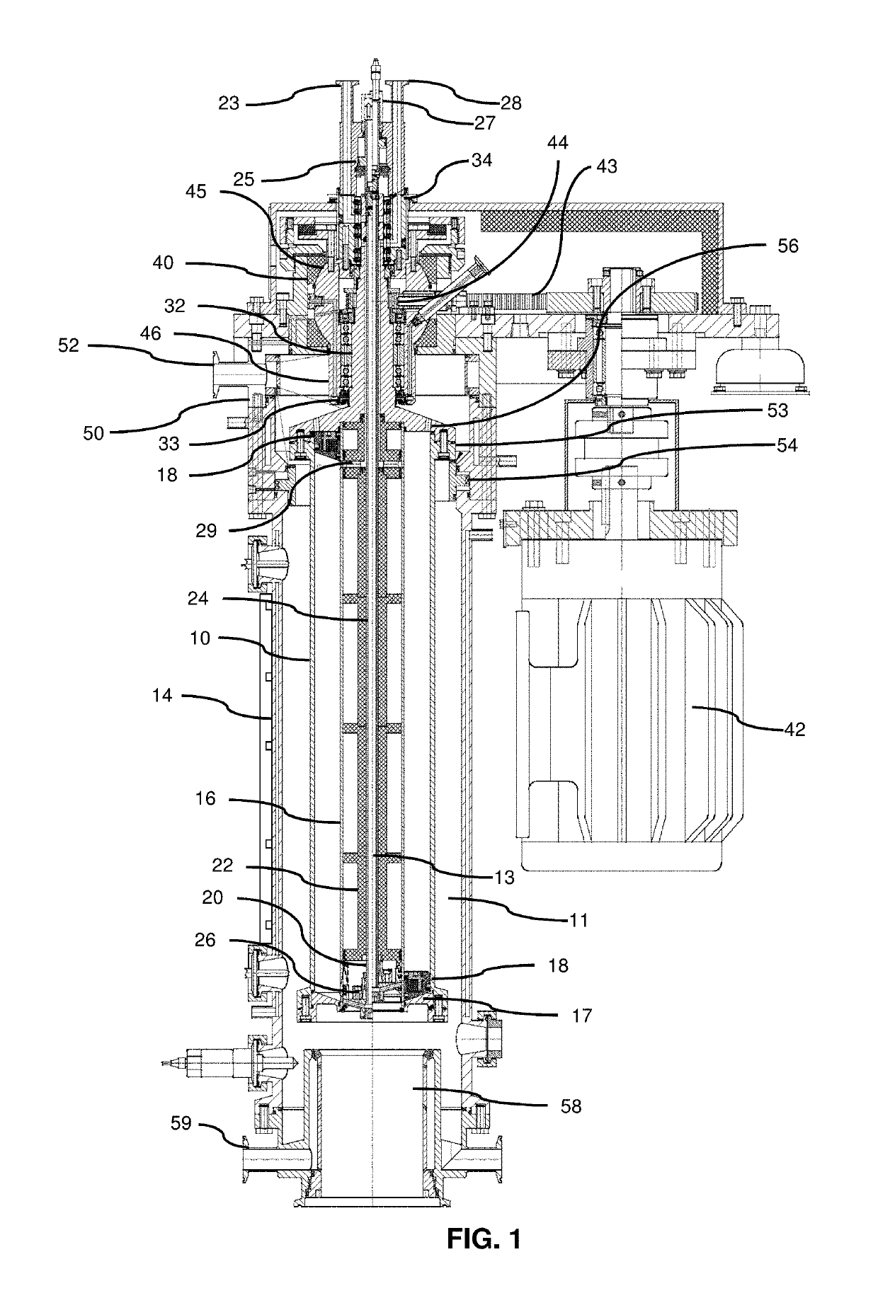
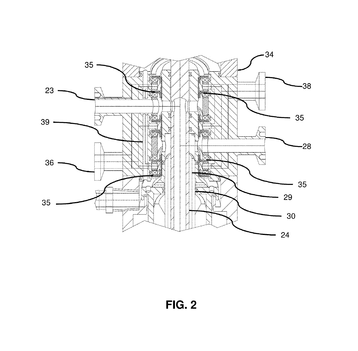
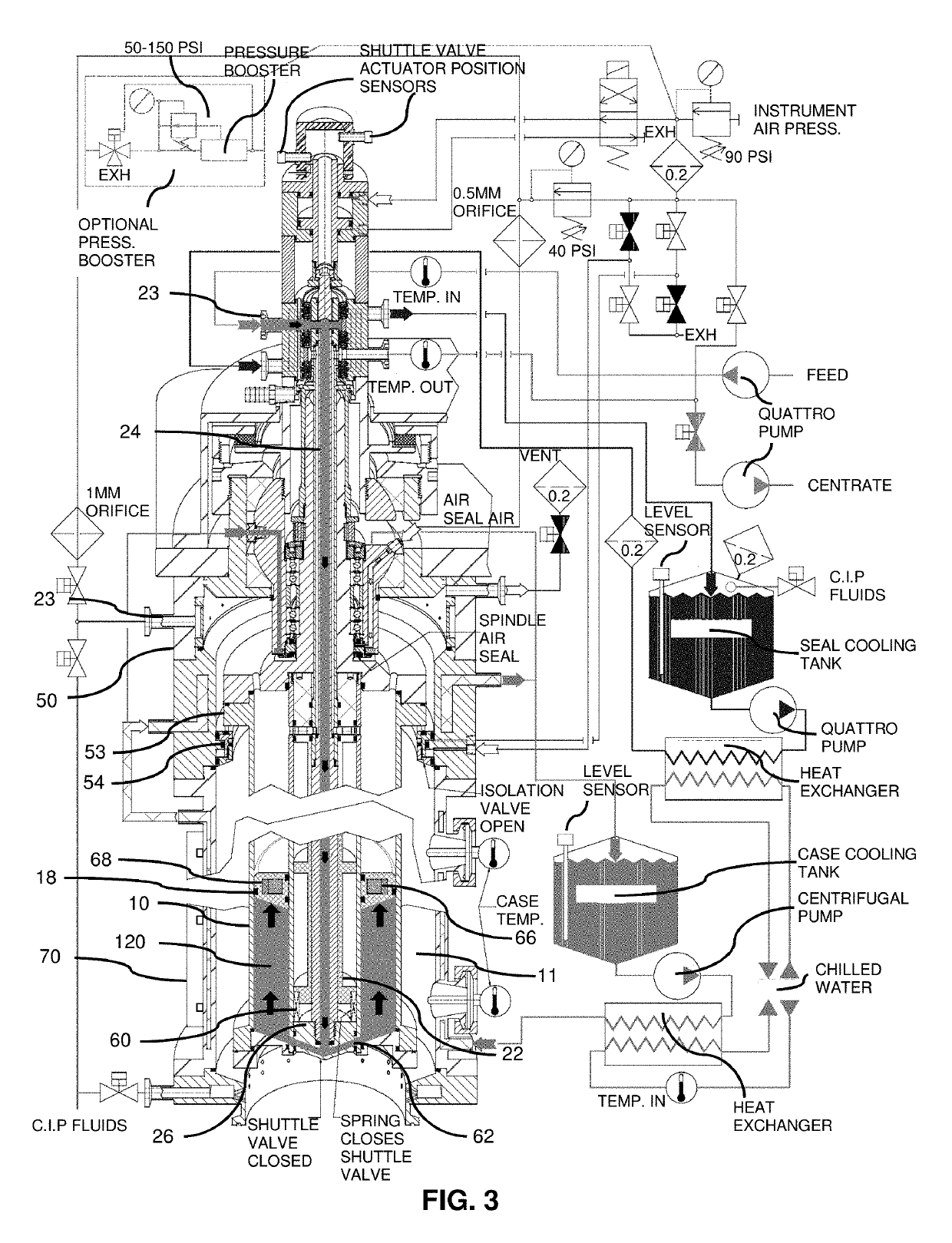
[0036]As described below and shown in the accompanying drawings, the centrifugal separator described herein includes a cylindrical separator bowl and an annular piston surrounding a core tube assembly for introducing a feed liquid, removing centrate, and a shuttle valve for extruding accumulated solids following centrifugation. Unlike centrifugal separators with a central piston assembly, centrifugal separators using the technology described herein can accommodate more solids, thus allowing processing of feed liquids having a higher percentage of solids by volume. The use of a central core tube to feed liquid also prevents wave agitation of the feed liquid during separation and increasing the efficiency of solids separation. The use of a core tube to feed liquid also results in dryer solids having lower moisture content and a clearer centrate having a lower suspended solids content that is removed during centrifugation. Further, foaming and oxidation of feed liquid is reduced during...


PUM


Abstract

A centrifugal separator includes a cylindrical bowl, a core tube assembly, and an annular piston disposed around the core tube assembly and inside the inner surface of the bowl. Feed liquid is injected down the core tube assembly into the lower portion of the bowl, raising the annular piston. During a separation mode, the bowl rotates at high speed, separating solids from the feed liquid to accumulate along the inner surface of the bowl, while collecting clarified centrate as it exits the top of the bowl and through the core tube assembly. Following solids accumulation, bowl rotation is stopped and residual liquid is pumped from the bowl. In a solids discharge mode, the annular piston is urged downward along a vertical axis in response to compressed gas. The downward movement of the piston forces accumulated solids from the bowl via an opening in the lower end thereof.

Description

CROSS-REFERENCE TO RELATED APPLICATIONS[0001]This application claims the benefit of priority to U.S. Patent Application No. 62 / 506,723, filed on May 16, 2017, the entire disclosure of which is incorporated herein by reference.FIELD[0002]The instant disclosure relates to centrifuges, and in particular to a centrifuge enabling automatic discharge of solids that accumulate during separation.BACKGROUND[0003]Many different types of centrifugal separators are known for separating heterogeneous mixtures into components based on specific gravity. A heterogeneous mixture, which may also be referred to as feed material or feed liquid, is injected into a rotating bowl of the separator. The bowl rotates at high speeds and forces particles of the mixture, having a higher specific gravity, to separate from the liquid by sedimentation. As a result, a dense solids cake compresses tightly against the surface of the bowl, and the clarified liquid, or “centrate”, forms radially inward from the solids ...

Claims


Application Information

Patent Timeline
Patent Type & Authority Patents(United States)
IPC IPC(8): B04B11/05B04B1/02B04B11/08B04B11/06B04B9/12B04B5/04
CPCB04B11/05B04B9/12B04B11/08B04B1/02B04B11/06B04B2005/0485
Inventor CARR, ROBERT BRET
Owner CARR ROBERT BRET
Learn More