Battery pack for a hand-held power tool and method for manufacturing a current-carrying connection, preferably a cell connector of a battery pack for a hand-held power tool

a technology for hand-held power tools and cell connectors, which is applied in the direction of batteries, cell components, electrical apparatuses, etc., can solve the problems of large parasitic shunts, unsatisfactory effects, and inability to meet the requirements of the process, and achieve high conductivity

Active Publication Date: 2019-10-29
ROBERT BOSCH GMBH
View PDF6 Cites 0 Cited by
  • Summary
  • Abstract
  • Description
  • Claims
  • Application Information

AI Technical Summary

Benefits of technology

[0011]A second object of the present invention is to circumvent the disadvantages listed above and provide a method for welding a cell connector on a pole of a battery cell which is situated in a cell bracket of a battery pack for a hand-held power tool, the cell connector having a high conductivity, the welding process is well controllable, and which is thereby preferably flexibly usable, inexpensive, and simple to carry out.
[0015]In this way, a large, effective conductor cross section of the cell connector is available in total for the power transmission, whereby the low conductor resistance of the cell connector, required for operating the battery pack, may be implemented. During the individual welding processes, which are carried out only at the respective individual partial cross sections, i.e., at the separate conductors, the resistance in the parasitic shunt is, in contrast, relatively high, so that a large part of the welding current is actually available for melting the weld nugget, which enables a good controllability of the process and a high quality of the connection.
[0017]This specific embodiment advantageously adds to the advantages described above with respect to the relationship of the electrical conductivity of the cell connector during the establishment of the connection and in the installed state, that the available installation space is utilized very well by the arrangement of the individual conductors in the stack.
[0019]In yet another alternative specific embodiment, the cell connector is a continuous conductor which, by bending at least one bending point, is guided back and forth between the poles of the battery cells and thus forms a stack structure. This may be advantageous in terms of manufacturing considerations if in this way process steps for separating multiple conductors may be saved.
[0021]In one alternative specific embodiment, the overlapping cross-sectional areas are connected to one another by a cross-sectional part which has a bending radius, the angle α over which the bend radius extends being between 170° and 190°, preferably 180°. In this way, a continuous, easy to handle conductor may be used, which, however, offers the same advantages as described above with respect to the conductivity.
[0041]Basically, lithium-ion cells in particular may be used as the battery cells, since it is particularly possible with lithium-ion cells to integrate multiple battery cells into battery cell blocks, in which multiple battery cells are connected in parallel. It is thereby particularly advantageous that the cell bracket may accommodate battery cells having different diameters and lengths, whereby the use of the cell bracket or the cell carrier in different battery packs may be achieved.

Problems solved by technology

Undesirable effects which oppose an efficient process control result, for example, from the contact resistance prevailing between the electrodes and the join partners, and from the so-called parasitic shunt which flows through the join partners between the electrodes, but not through the weld nugget.
This portion of the current does not contribute to the Joule heating of the weld nugget, and in this sense is lost to the welding process, and may, in the worst case, lead to damage at unforeseen points.
It has thereby proven to be problematic that the cell connector is to have a preferably good conductivity between the battery cells in the installed state, as this ensures that the parasitic shunt becomes large relative to the usable welding current.
A cell connector, intended for use in the battery pack, having a preferably low electrical resistance thus generally opposes an efficient and stable resistance spot welding process.

Method used


Image

  • Battery pack for a hand-held power tool and method for manufacturing a current-carrying connection, preferably a cell connector of a battery pack for a hand-held power tool
  • Battery pack for a hand-held power tool and method for manufacturing a current-carrying connection, preferably a cell connector of a battery pack for a hand-held power tool
  • Battery pack for a hand-held power tool and method for manufacturing a current-carrying connection, preferably a cell connector of a battery pack for a hand-held power tool

Examples


Embodiment Construction

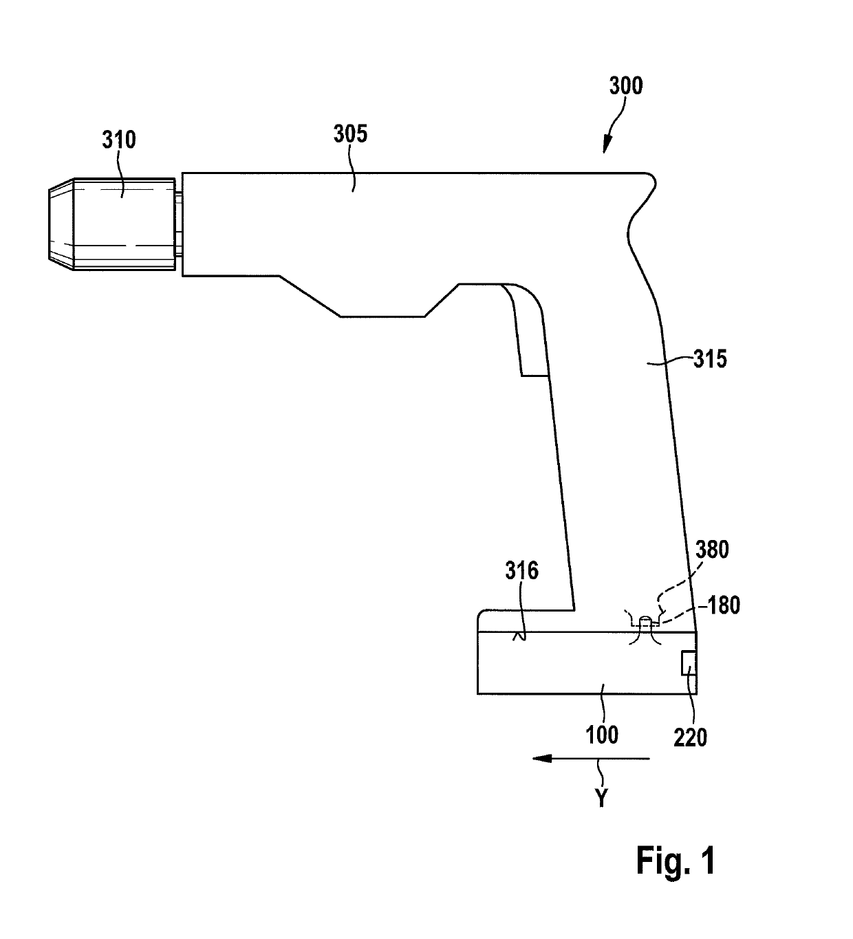
[0051]FIG. 1 shows an electrical device designed as a hand-held power tool 300. According to the specific embodiment shown, hand-held power tool 300 is mechanically and electrically connectable to the battery pack 100 for off-grid power supply. Hand-held-power tool 300 in FIG. 1 is designed for example as a cordless combi drill. However, it is pointed out that the present invention is not limited to cordless combi drills, but instead may be used in different hand-held power tools 300 which are operated by a battery pack 100. Hand-held power tool 300 has a base body 305, on which a tool holder 320 is fixed, and a handle 315 including an interface 380, on which a corresponding interface 180 of battery pack 100 according to the present invention is situated, in this case in the locked position. Battery pack 100 is configured as a slide-in battery pack.

[0052]Upon mounting battery pack 100 on hand-held power tool 300, an accommodating arrangement provided on hand-held power tool 300, e.g...


PUM

PropertyMeasurementUnit
bending angleaaaaaaaaaa
angleaaaaaaaaaa

Abstract

A battery pack for a hand-held power tool including a battery pack housing, the battery pack housing accommodating at least two battery cells, and at least one cell connector for connecting the battery cells in parallel and / or in series, the cell connector being connected to a pole of the first battery cell and to a pole of the second battery cell using a welding method, the cell connector including at least two at least partially overlapping, current-carrying cross-sectional areas in an unwelded area between the battery cells.

Description

CROSS REFERENCE[0001]The present application claims the benefit under 35 U.S.C. § 119 of German Patent Application No. 102015205200.1 filed on Mar. 23, 2015, which is expressly incorporated herein by reference in its entirety.FIELD[0002]The present invention relates to a battery pack for a hand-held power tool, and a method for manufacturing a current-carrying connection, preferably a cell connector of a battery pack for a hand-held power tool.BACKGROUND INFORMATION[0003]Electric hand-held power tools, for example, impact screw drivers, drills, angle grinders, jigsaws, circular saws, or planers for the needs of craftsmen or handymen usually have either an AC motor or a DC motor as the drive motor. While the former is generally supplied with alternating current from the grid via a power cable, the electrical power for supplying the DC motor generally comes from a so-called battery back, a rechargeable battery in a housing which may be coupled to the housing of the hand-held power too...

Claims


Application Information

Patent Timeline
Patent Type & Authority Patents(United States)
IPC IPC(8): H01M2/20H01M2/10H01M50/503H01M50/51H01M50/512H01M50/516
CPCH01M2/204H01M2/1055H01M2220/30H01M10/0525H01M50/51H01M50/503H01M50/512H01M50/516Y02E60/10H01M50/213
Inventor ZAHN, WOLFSCHMEHL, FLORIANBAUMGARTNER, JOSEPH
Owner ROBERT BOSCH GMBH
Why Eureka
Try Eureka