Pop-up wheel device for use in material handling equipment

a technology for material handling equipment and pop-up wheels, which is applied in the direction of rollers, shafts and bearings, linear bearings, etc., can solve the problems of damage to the cap and/or the housing, the primary ball or other internal components of the pop-up unit can become worn and/or dirty, and the primary ball or other internal components of the unit can be easily replaced, etc., to facilitate the replacement of certain components, easy assembly, and easy mass production

Active Publication Date: 2019-11-05
OMTEC CORP
View PDF62 Cites 4 Cited by
  • Summary
  • Abstract
  • Description
  • Claims
  • Application Information

AI Technical Summary

Benefits of technology

[0013]It is still another object of the present invention to provide a device as described above that can readily be mass-produced, that is easy to assemble, and that easily permits the replacement of certain components.

Problems solved by technology

For example, once the internal components of the pop-up unit have been placed in the housing and the cap has been secured to the housing, the internal components of the pop-up unit, such as the primary ball, cannot be removed from the housing without removing the cap from the housing.
However, removal of the cap from the housing is often cumbersome and / or may cause damage to the cap and / or the housing.
This is unfortunate because the primary ball or other internal components of the unit can become worn and / or dirty over time.
As a result, because of the limited contact area between the primary ball and an article positioned thereon, it can be difficult at times to steer the article in a desired direction using the primary ball.
Still another shortcoming noted by the present inventor is that, over time, the rubber seal positioned around the piston tends to become worn.
Such wear may be caused, for example, by the repeated sliding of the seal against the inner side wall of the housing as the piston is raised and lowered.
As can be appreciated, the wearing of the seal may negatively impact the performance of the pop-up unit since leaks in or around the seal allow pressurized gas to escape from the housing, thereby making it more difficult to raise the piston when desired.
Consequently, as compared to a pop-up unit, whose ball or stop may be raised and lowered as desired, the wheel or roller of the above-described unidirectional rotating support assembly is fixed in a raised position and cannot be lowered when repositioning or steering of an article is not desired.
The present inventor has found this to be disadvantageous as the raised wheel or roller limits the amount of usable surface area of the work surface.

Method used


Image

  • Pop-up wheel device for use in material handling equipment
  • Pop-up wheel device for use in material handling equipment
  • Pop-up wheel device for use in material handling equipment

Examples


Embodiment Construction

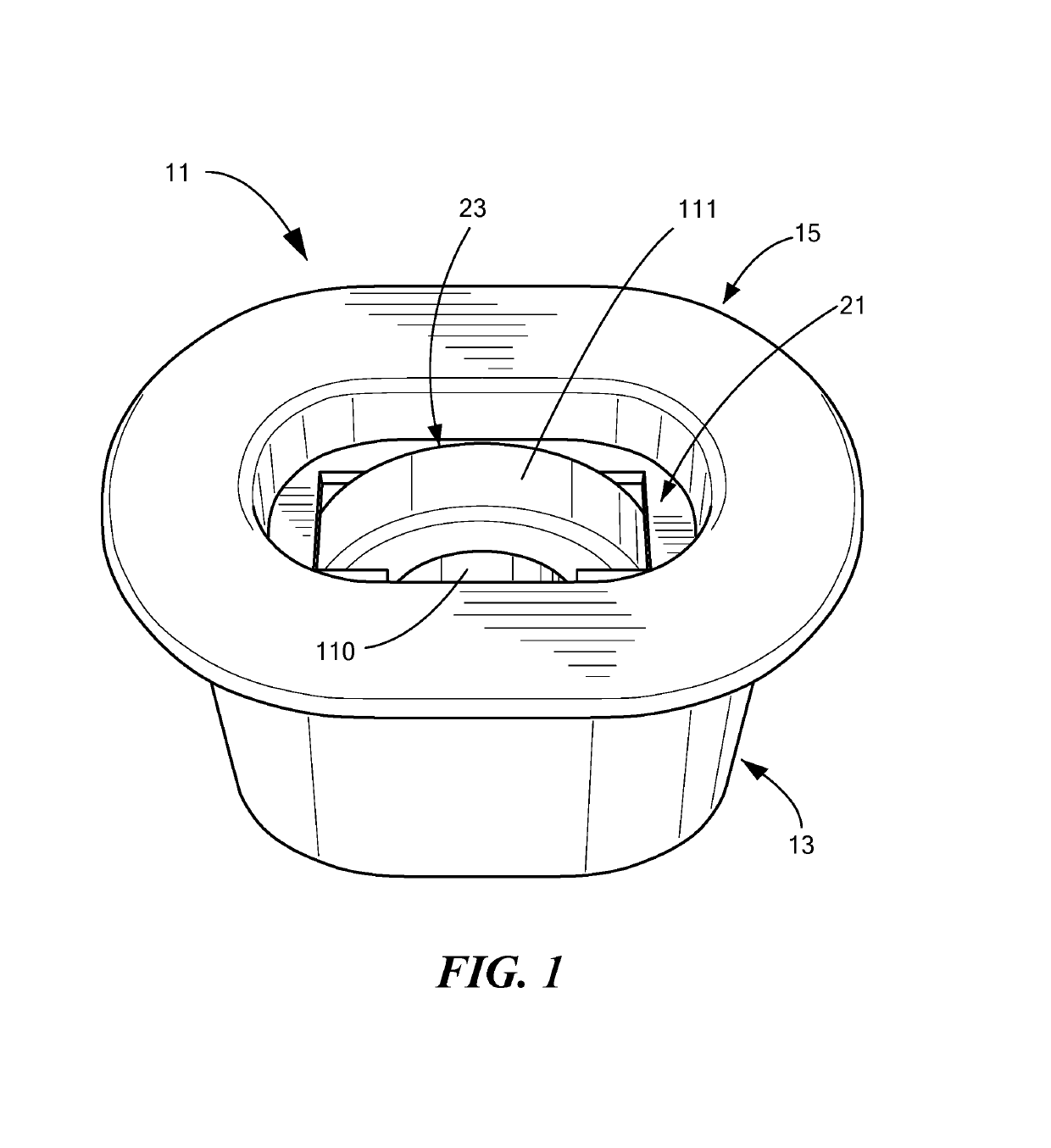
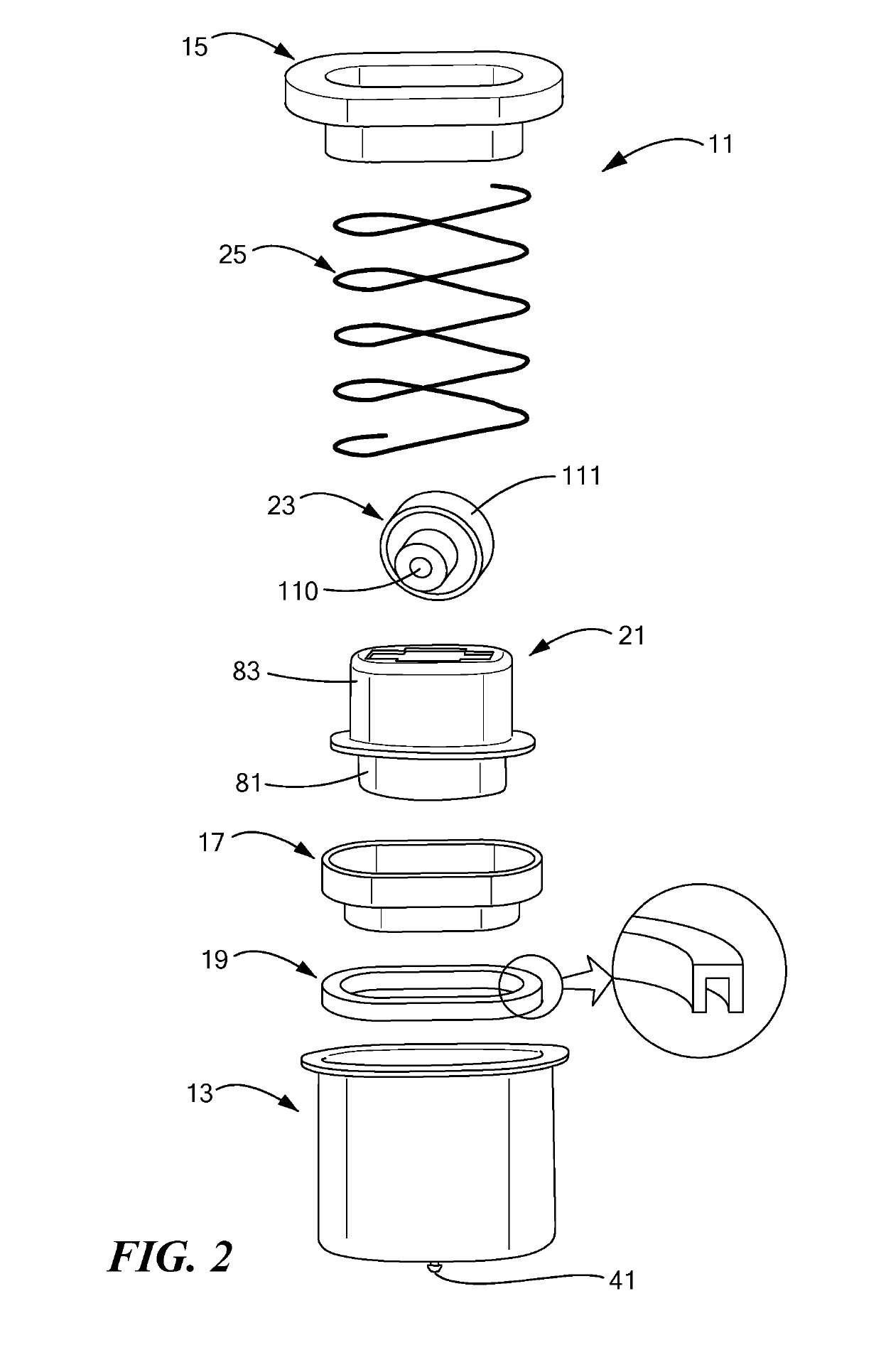
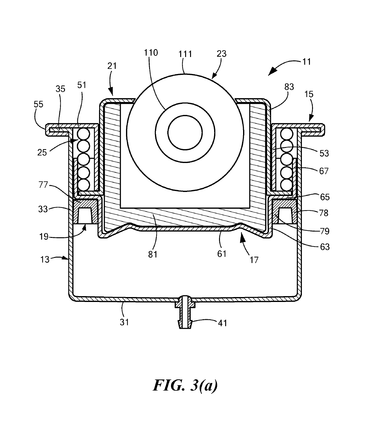
[0049]Referring now to FIGS. 1, 2, 3(a), and 3(b), there are shown various views of one embodiment of a pop-up wheel device that is suitable for use in material handling equipment, the pop-up wheel device being constructed according to the present invention and being represented generally by reference numeral 11. For clarity, certain details of pop-up wheel device 11 that are discussed elsewhere in this application or that are not critical to an understanding of the invention may not be shown in one or more of FIGS. 1, 2, 3(a), and 3(b) or may be shown therein in a simplified manner.

[0050]Pop-up wheel device 11 may comprise a housing 13, a cap 15, a piston 17, a seal 19, a wheel mount 21, a wheel assembly 23, and a coiled spring 25.

[0051]Housing 13, which is also shown separately in FIGS. 4(a) through 4(d), may comprise a generally hollow container or can having a track-shaped transverse cross-section, i.e., two generally parallel straight sides and two opposed curved ends. Instead ...


PUM


Abstract

A pop-up wheel device for use in material handling equipment. In one embodiment, the pop-up wheel device includes a housing, which is a can of generally track-shaped transverse cross-section. A nipple is mounted in the housing bottom to permit fluid under pressure to pass to and from the interior of the housing. A cap, which includes a central opening, is positioned over and is secured to the housing. A piston is slidably mounted within the housing between a lower position and an upper position. A seal is fitted around a lower portion of the piston and creates an air-tight chamber between the piston and the housing. A spring biases the piston towards the lower position. A wheel that is freely rotatable in one direction is coupled to the piston using a wheel mount. The wheel may be removed from the wheel mount without removing the cap from the housing.

Description

BACKGROUND OF THE INVENTION[0001]The present invention relates generally to material handling equipment and relates more particularly to pop-up units for use in material handling equipment.[0002]The manufacture and / or packaging of many types of commercial articles often involves the use of material handling equipment. One example of material handling equipment is a bench or workstation at which certain assembly or packaging steps for an article are performed. Another example of material handling equipment is a conveyor system for transporting an article from one workstation to another.[0003]As can readily be appreciated, an article that is seated on top of a bench or workstation often must be repositioned or rotated thereon so that certain assembly or packaging steps can be performed. Similarly, it is often the case that the direction in which an article is traveling along a conveyor system must be altered or its movement altogether stopped. For these reasons, various types of repos...

Claims


Application Information

Patent Timeline
Patent Type & Authority Patents(United States)
IPC IPC(8): B65G13/12F16C13/00F15B15/14B65G39/09F16C29/04
CPCB65G39/09B65G13/12F15B15/1447F16C13/006F15B15/1433F16C2326/58F16C29/04
Inventor MASCIARELLI, SHAWN MORRIS
Owner OMTEC CORP
Why Eureka
Try Eureka