Gas turbine engine

a technology of gas turbine engine and gas turbine engine, which is applied in the direction of machines/engines, efficient propulsion technologies, instruments, etc., can solve the problems of increasing the footprint inside the ecu that is already challenged, increasing the footprint of the ecu, and increasing the cost of the ecu, so as to improve the electromagnetic interference measures, reduce the weight and cost, and the effect of small footprin

Active Publication Date: 2019-11-12
HONEYWELL LK GLOBAL PATENT SERVICES
View PDF14 Cites 2 Cited by
  • Summary
  • Abstract
  • Description
  • Claims
  • Application Information

AI Technical Summary

Benefits of technology

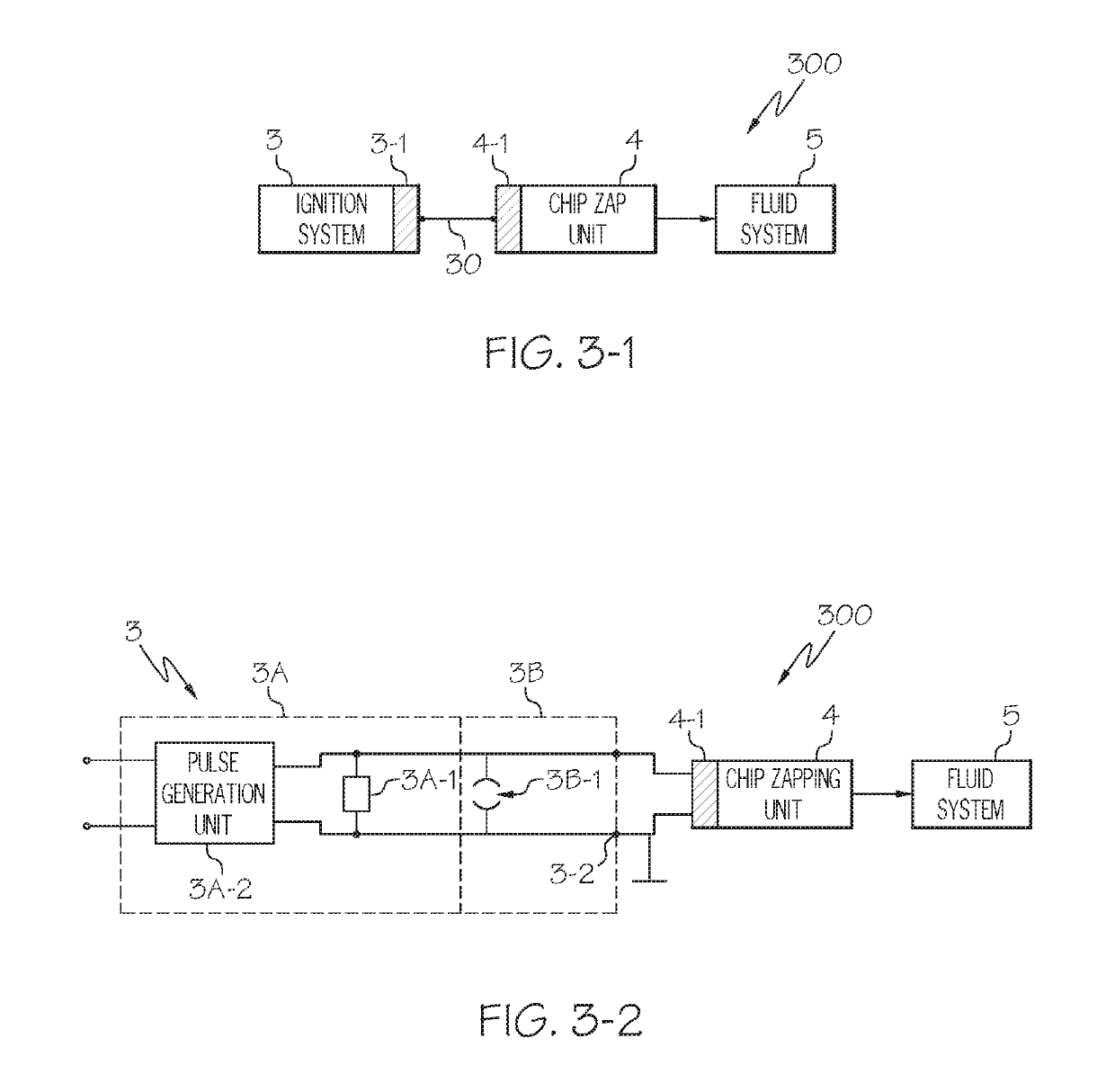
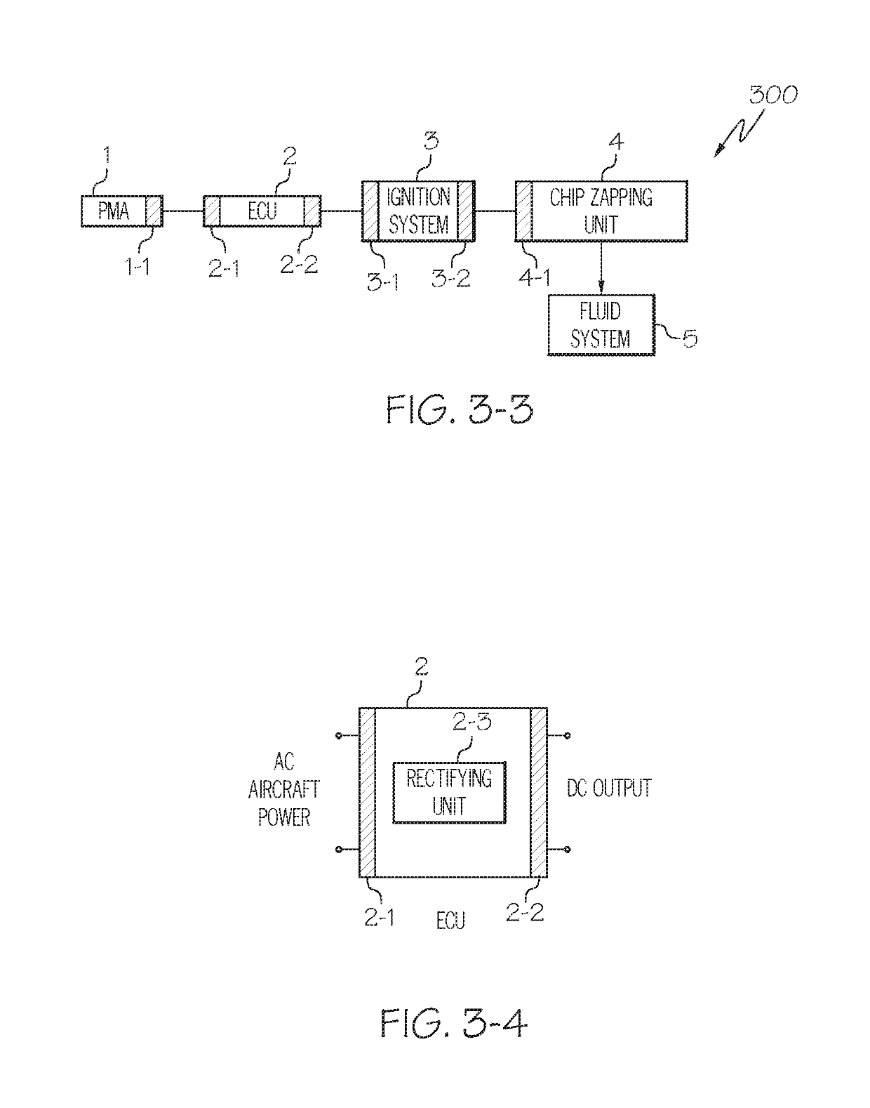
[0011]According to these embodiments of the invention, the technical problem of energy generation inside the electronic control unit for the chip zapper on gas turbine engines is solved. That is, according to the embodiments of the invention, excess energy that is stored in the ignition exciter and discharged to the ground plane when the ignition exciter is commanded off is used as operational energy for driving the chip zapping unit. This replaces the space intensive energy generation units and their electrical circuitry inside the electronic control unit. Therefore, according to the embodiments of the invention no additional energy generation units are needed, neither in the electronic control unit nor elsewhere in the gas turbine engine because the somewhat wasted energy already present during discharge in the ignition exciter is used as operational energy for the chip zapping unit. Furthermore, the electromagnetic interference problem inside the electronic control unit is solved because high and low energy units are not placed next to each other.

Problems solved by technology

Furthermore, a significant number of metal chips in the transmission fluid can also indicate general mechanical problems with a transmission.
Metal particles in a lubrication system are undesirable.
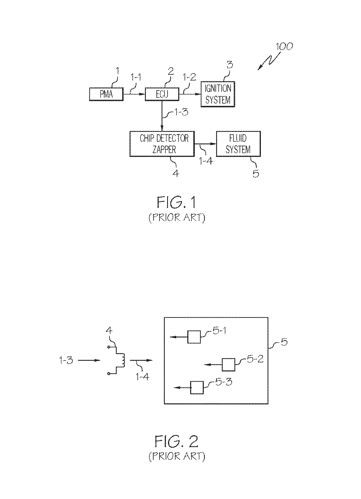
As may be appreciated, the circuits necessary for this generally increase the footprint inside an ECU that is already challenged for space.
Furthermore, such high energy power generation inside the ECU can result in additional costs to the ECU and decrease the overall reliability of the ECU.
For example, such harnesses increase the likelihood of electromagnetic interference and lightning threats in the energy generation system.
Therefore, generating the high energy pulses for the chip zapper inside the electronic control unit also presents potential challenges if high energy and low energy control units are arranged close to each other in the limited space of the ECU.
Thus, while presently known electronic control units and chip zappers are generally safe, reliable and robust, gas turbine engines with an electronic control unit including an energy generation unit for generating operational energy for the chip zapper can exhibit the above described drawbacks, in particular a large footprint inside the ECU, and increased weight due to the additional circuits in the electronic control unit and the potential challenges of electromagnetic interference and interaction as well as lightning threats.
In the conventional operational energy generation system in FIG. 1 and FIG. 2, as already partially described above, the footprint inside the conventional electronic control unit 2 is already very challenged for space.
Furthermore, since quite substantial energy is needed for driving the chip detector / zapper 4, there may be also thermal problems inside the conventional electronic control unit, in addition to potential electromagnetic interference (EMI) and lightning problems.
However, it was realized that the shunt circuitry energy during discharge is effectively wasted energy as it is discharged to the ground plane in conventional systems.
The described system additionally enhances electromagnetic interference measures and thermal problems conventionally existing in the electronic control unit of the prior art.

Method used


Image

  • Gas turbine engine
  • Gas turbine engine
  • Gas turbine engine

Examples


Embodiment Construction

[0025]Hereinafter, embodiments of the present invention are described with reference to the attached drawings. However, it should be noted that the following detailed description is merely exemplary in nature and is not intended to limit the invention or the application and uses of the invention. As used herein, the word “exemplary” means “serving as an example, instance, or illustration”. Thus, any embodiment described herein as “exemplary” is not necessarily to be construed as preferred or advantageous over other embodiments. All the embodiments described herein are exemplary embodiments provided to enable persons skilled in the art to make or use the invention and not to limit the scope of the invention which is defined by the claims. Furthermore, there is no intention to be bound by any expressed or implied theory presented in the preceding technical field, background, brief summary of the following detailed description.

[0026]Referring now to FIG. 1, a functional block diagram o...


PUM

PropertyMeasurementUnit
energyaaaaaaaaaa
electrical energyaaaaaaaaaa
operational energyaaaaaaaaaa

Abstract

An energy generation system for generating energy to be supplied to a chip zapping unit of for example a gas turbine engine comprises an ignition system, e.g. that of the gas turbine engine, the ignition system having an energy output and configured to supply operational energy to the energy output, and the chip zapping unit having an energy input, the energy input coupled to the energy output of the ignition system to receive the operational energy therefrom. Such an energy generation system generates the operational energy needed for the chip zapping unit directly from the ignition system thus avoiding pulse generation circuitry inside an electronic control unit.

Description

TECHNICAL FIELD[0001]The present invention generally relates to gas turbine engines and more particularly relates to a chip zapping unit employed in a lubrication system of the gas turbine engine for removing metal parts from the lubrication fluid and even more particularly to an energy generation system and method for generating the operational energy needed by the chip zapping unit.BACKGROUND[0002]A typical gas turbine engine includes at least a compressor section, a combustion section and a turbine section. In the compressor section and in the turbine section typically lubrication fluids are necessary. Lubrication may also be necessary in other parts of the gas turbine engine or even in an aircraft which is powered by the gas turbine engine, for example in the transmission or gearbox of a helicopter. During prolonged operation metal chips may accumulate in the transmission fluid or lubrication fluid. The metal chips may be generated during normal operation (despite the presence o...

Claims


Application Information

Patent Timeline
Patent Type & Authority Patents(United States)
IPC IPC(8): F02C7/266B03C1/28F01D25/18F16N29/04G01N15/10
CPCF01D25/18G01N15/1031F02C7/266F16N29/04B03C1/28Y02T50/671F05D2260/99F05D2260/98Y02T50/60
Inventor KELLY, JEFF M.
Owner HONEYWELL LK GLOBAL PATENT SERVICES
Why Eureka
Try Eureka