
Implantable fastener for attachment of a medical device to tissue

a technology of medical devices and fasteners, which is applied in the field of surgical staples, can solve the problems of recurrent ptosis, recurrent ptosis, and only slowing down recurrent ptosis, and achieves the effects of improving the stability and stability of the patient's body

Active Publication Date: 2019-12-17
TEPHA INC
View PDF21 Cites 1 Cited by
  • Summary
  • Abstract
  • Description
  • Claims
  • Application Information

AI Technical Summary

Benefits of technology

Enables precise and adjustable fixation of medical devices like surgical meshes, reducing operating time and improving positioning accuracy, even in restricted access areas, by allowing for easy repositioning of implants without the need for suture or anchor removal and replacement.

Problems solved by technology

For example, skin laxity, loss of muscle tone, and attenuation of ligaments can result in ptosis (drooping) of the breast.
These approaches almost invariably result in recurrent ptosis, since the surgeon is merely relying on the aging and sagging surrounding tissues that have already failed to provide the necessary support to maintain a normal appearance.
At most, these techniques only slow recurrent ptosis by creating internal scars that provide limited reinforcement.
The correct positioning of the breasts can be particularly difficult because surgeons generally work with the patient lying horizontal on the operating table.
Since the mesh is usually fixated to the patient's tissue using either sutures, screws, or anchors, the process of optimizing breast shape and position can be difficult because it may require, for example, sutures to be cut and placed in a different position or for screws and anchors to be removed and / or replaced.
In these procedures, it is often difficult for the surgeon to anchor the mesh in the lateral position because: (i) access is restricted; (ii) little tissue is available for fixation; and (iii) nerves in the lateral position, which should not be trapped, make fixation challenging.
Surgeons have attempted to use barbed sutures and staples for fixation when access to a fixation site is restricted, however, these fixation systems cannot be adjusted once implanted.

Method used


Image

  • Implantable fastener for attachment of a medical device to tissue
  • Implantable fastener for attachment of a medical device to tissue
  • Implantable fastener for attachment of a medical device to tissue

Examples


example 1

re of a Repositionable Fastener with Swivel Anchors by Laser Cutting

[0138]A thin oriented film made of poly-4-hydroxybutyrate (P4HB) with a uniform thickness of 0.7 mm, was placed on a laser-cutting table (FIG. 9 shows the laser setup). The setup includes a laser control unit (92), a laser head with CAD (computer aided design) XYZ motion (98), a work station (94), a film substrate (102) and a laser cut pattern to form a flexible anchor (96). A CO2 laser source was located above the film, and was used to cut a pre-determined pattern of the perimeter of the repositionable fastener, 30 swivel anchors, and 24 pores (holes) as shown in FIG. 8. To create the pattern of swivel anchors and the perimeter of the fastener, the laser power was set between 40 to 60 watts with a focal distance ranging from 0.5 to 2.0 cm. Once cutting was complete, the cut shape of film was separated from the excess film material, and placed onto an angle plate consisting of a metal base plate with orientation pin...

example 2

re of a Repositionable Fastener with Swivel Anchors by Die Cutting

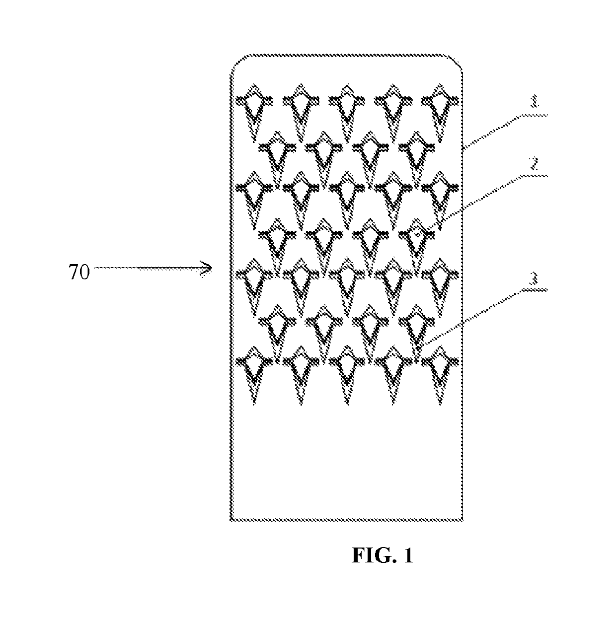
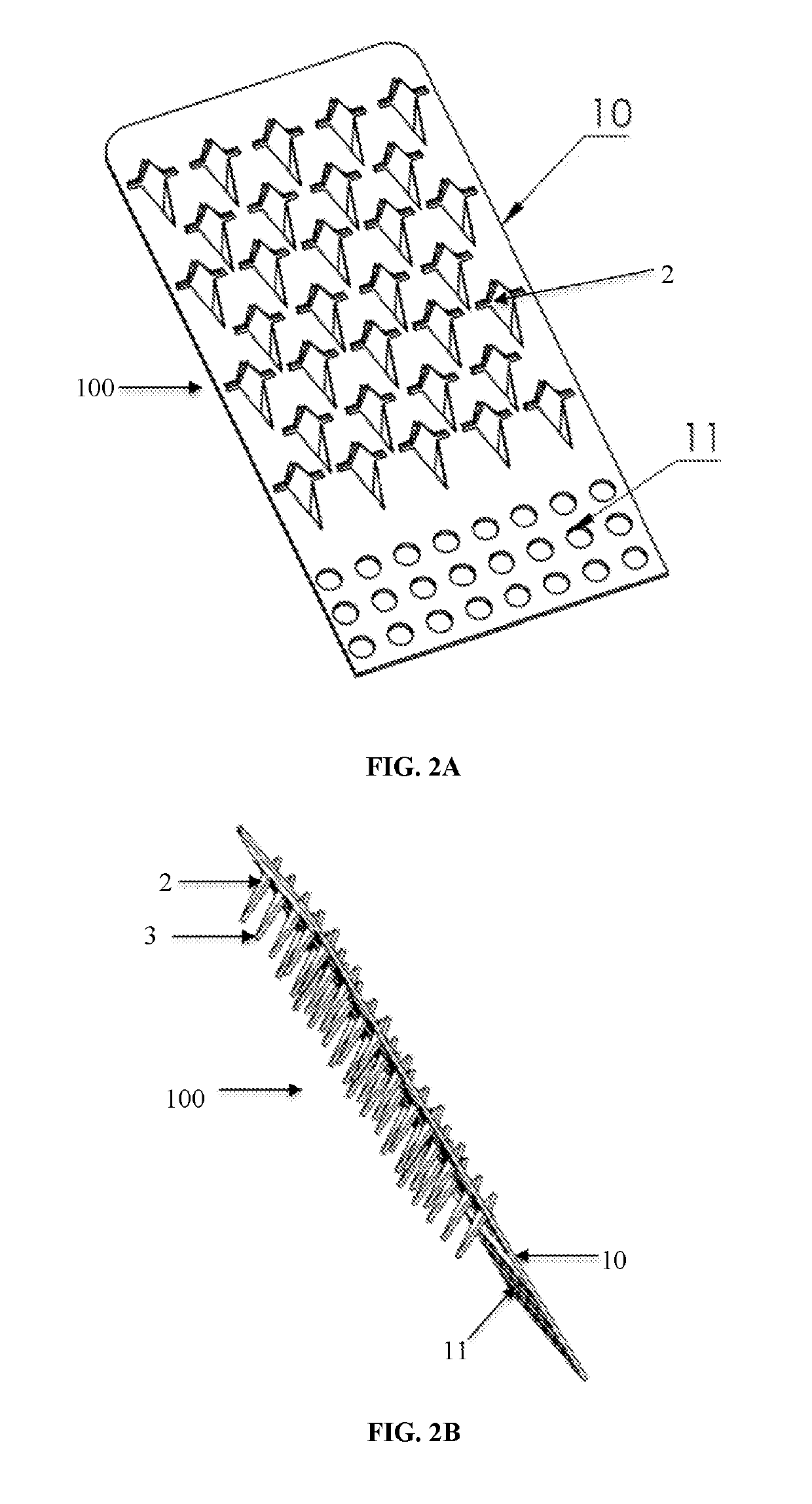
[0140]A thin oriented film made of poly-4-hydroxybutyrate (P4HB) of uniform thickness (ranging from 0.5 to 1.0 mm) was cut to produce the anchor pattern shown in FIG. 2 by pressing a custom steel rule die onto the P4HB film instead of using a laser to cut the film as described in Example 1. The subsequent steps described in Example 1 wherein the swivel anchors were produced from the cut film with the metal base plate and using orientation pins as illustrated in FIG. 10 was used to produce the heat-set repositionable fastener with swivel anchors.

example 3

re of a Repositionable Fastener with Swivel Anchors by Injection Molding

[0141]A two-part mold with mating cavities was machined to generate the pattern shown in FIG. 1. Molten poly-4-hydroxybutyrate (P4HB) was injected through an injection port (gate) into the mold with a pressure of 4-6 tons to fill out the cavity formed by the assembled top and bottom halves of the mold, and was continued until excess polymer flowed out of the relief ports. The mold was allowed to cool to room temperature, disassembled, and the repositionable fastener removed from the mold. Excess polymer was trimmed form the molded fastener. An illustration of a two-part mold that can be used to produce a fastener with 4 swivel anchors is shown in FIG. 11.


PUM


Abstract

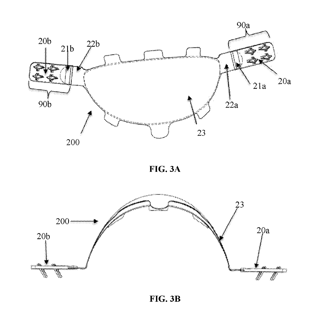
Implantable fasteners that can be repositioned after implantation, and implants including these repositionable implantable fasteners, have been developed. The fasteners are designed to fixate medical devices and other implantable components in the body, and can be adjusted after initial fixation in tissue to reposition the implanted medical device. The fasteners include a plurality of tissue retainers emanating from a supportive backing, wherein the tissue retainers can swivel from the plane of the supportive backing to engage tissue. The fasteners are fixated in tissue by movement in a first direction, and can be removed when pulled in a direction opposite to the first direction. The fasteners may be attached to medical devices before or after implantation. In one embodiment, the implant is a mastopexy device in the form of a mesh and the repositionable fastener.

Description

CROSS-REFERENCE TO RELATED APPLICATIONS[0001]This application claims benefit of U.S. Provisional Application No. 62 / 241,841, filed Oct. 15, 2015, the contents of which are incorporated by reference herein in their entirety.FIELD OF THE INVENTION[0002]The present invention generally relates to the field of surgery, and more particularly, the invention relates to implants with one or more repositionable fasteners that facilitate attachment of the implant to tissue. The fastener has a plurality of tissue retainers that can swivel from a supportive backing and engage tissue. Medical devices may be fixated to tissue by attachment to the fastener, and engagement of the fastener in tissue. The fastener may be a part of the implant. The design of the fastener allows the medical device to be repositioned if necessary after initial implantation.BACKGROUND OF THE INVENTION[0003]Numerous plastic surgery procedures are performed each year to restore or correct the form or function of the body. M...

Claims


Application Information

Patent Timeline
Patent Type & Authority Patents(United States)
IPC IPC(8): A61B17/04A61B17/064A61B17/80A61F2/12A61F2/00A61B17/56A61B17/00
CPCA61F2/12A61B17/064A61B17/809A61F2/0063A61B17/0401A61F2002/0068A61B2017/00898A61F2220/0016A61B2017/561A61B2017/00796A61B2017/0464A61B2017/0641A61B2017/00889A61B2017/00004A61B2017/0437A61B2017/00792
Inventor LIMEM, SKANDERVAN NATTA, BRUCECRISTADORO, KEVIN
Owner TEPHA INC
Learn More