
Honeycomb structure and method for manufacturing the same

a honeycomb and structure technology, applied in the field of honeycomb structure, can solve the problems of insufficient strength of the honeycomb structure, and achieve the effect of suppressing the reduction of specific surface area, high strength, and sufficient strength

Active Publication Date: 2019-12-17
DENSO CORP
View PDF3 Cites 8 Cited by
  • Summary
  • Abstract
  • Description
  • Claims
  • Application Information

AI Technical Summary

Benefits of technology

The patent describes a honeycomb structure that has sufficient strength and can be sintered at a low temperature. The structure includes promoter particles and an inorganic binder phase made of mainly α-alumina. The binder phase is formed by aggregating mutually the binder particles and sintering them at a low temperature. This process results in a honeycomb structure that has a larger specific surface area and strength than the initial clay material. The ratio of the specific surface area after heating to before heating at 1200° C. is 90% or more, which indicates that the honeycomb structure is sintered at a low temperature. The low sintering temperature also reduces the reduction of the specific surface area because the promoter particles are less affected by the sintering process. The honeycomb structure is manufactured by mixing the promoter particles, inorganic binder materials, and a sintering assistant solution, molding the clay into the honeycomb shape, and sintering it at a low temperature. The inorganic binder materials are fully thermal decomposed, even at low temperatures, and bond with the promoter particles at high strength. This results in a honeycomb structure with the desired specific surface area and strength.

Problems solved by technology

However, when honeycomb structures are constructed using a promoter component, there is a problem that the promoter particles are not completely bonded to each other and thus the strength of the honeycomb structure is insufficient.

Method used


Image

  • Honeycomb structure and method for manufacturing the same
  • Honeycomb structure and method for manufacturing the same
  • Honeycomb structure and method for manufacturing the same

Examples


fifth examples

Second to Fifth Examples

[0032]The amounts of materials of honeycomb structure used in the following examples and comparative examples are each expressed in terms of parts by mass relative to 100 parts by mass of promoter particles (i.e. 100 parts by mass of first promoter particles and second promoter particles).

[0033]In a second example, a honeycomb structure was prepared in the same way as in the first example, except that the blending ratio of the inorganic binder material was changed to 5 parts by mass in terms of solid content.

[0034]In a third example, a honeycomb structure was prepared in the same way as in the first example, except that the blending ratio of the inorganic binder material was changed to 15 parts by mass in terms of solid content.

[0035]In a fourth example, a honeycomb structure was prepared in the same way as in the first example, except that the blending ratio of the sintering assistant was changed to 0.7 parts by mass in terms of oxide equivalent amount.

[0036...

tenth examples

Sixth to Tenth Examples

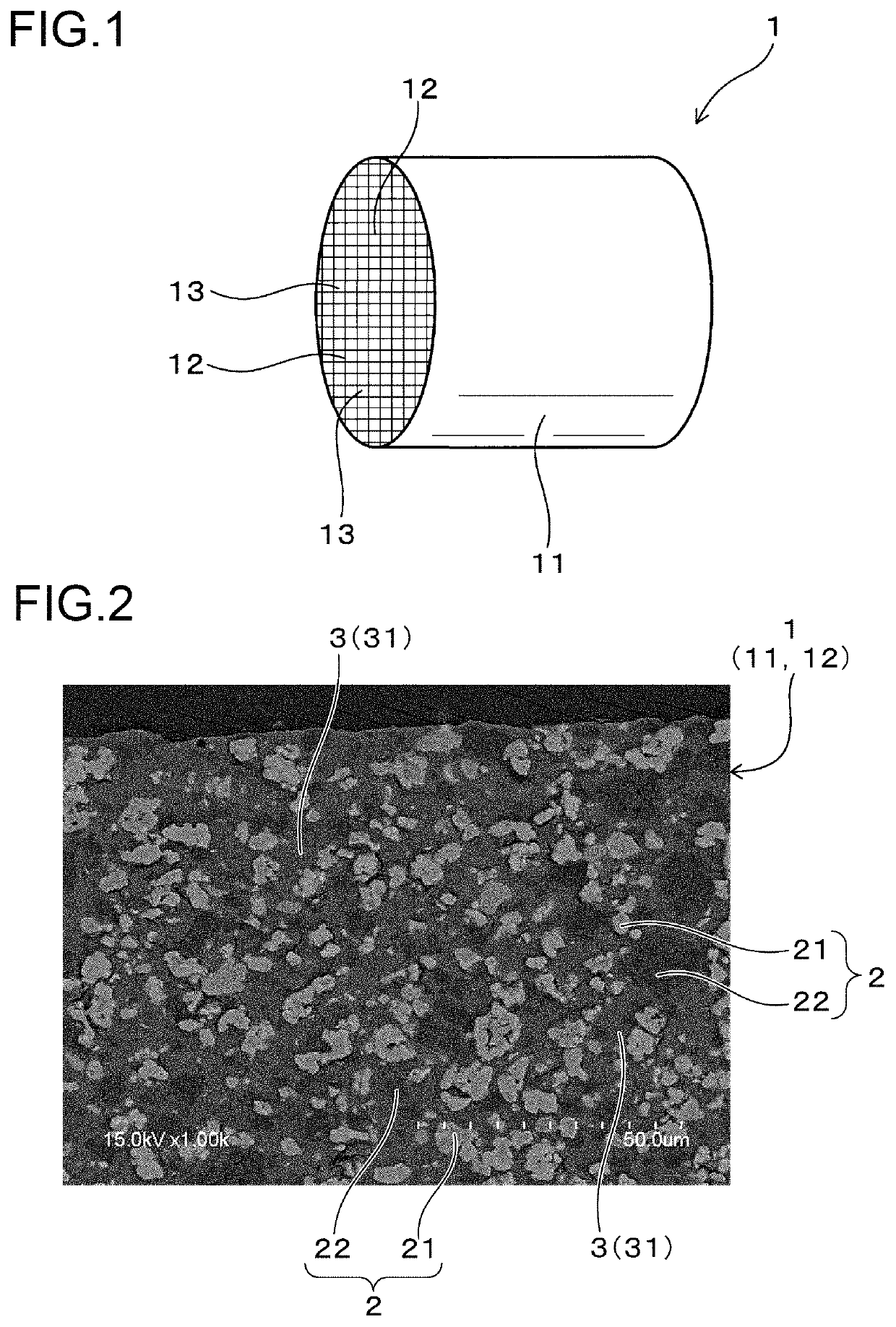
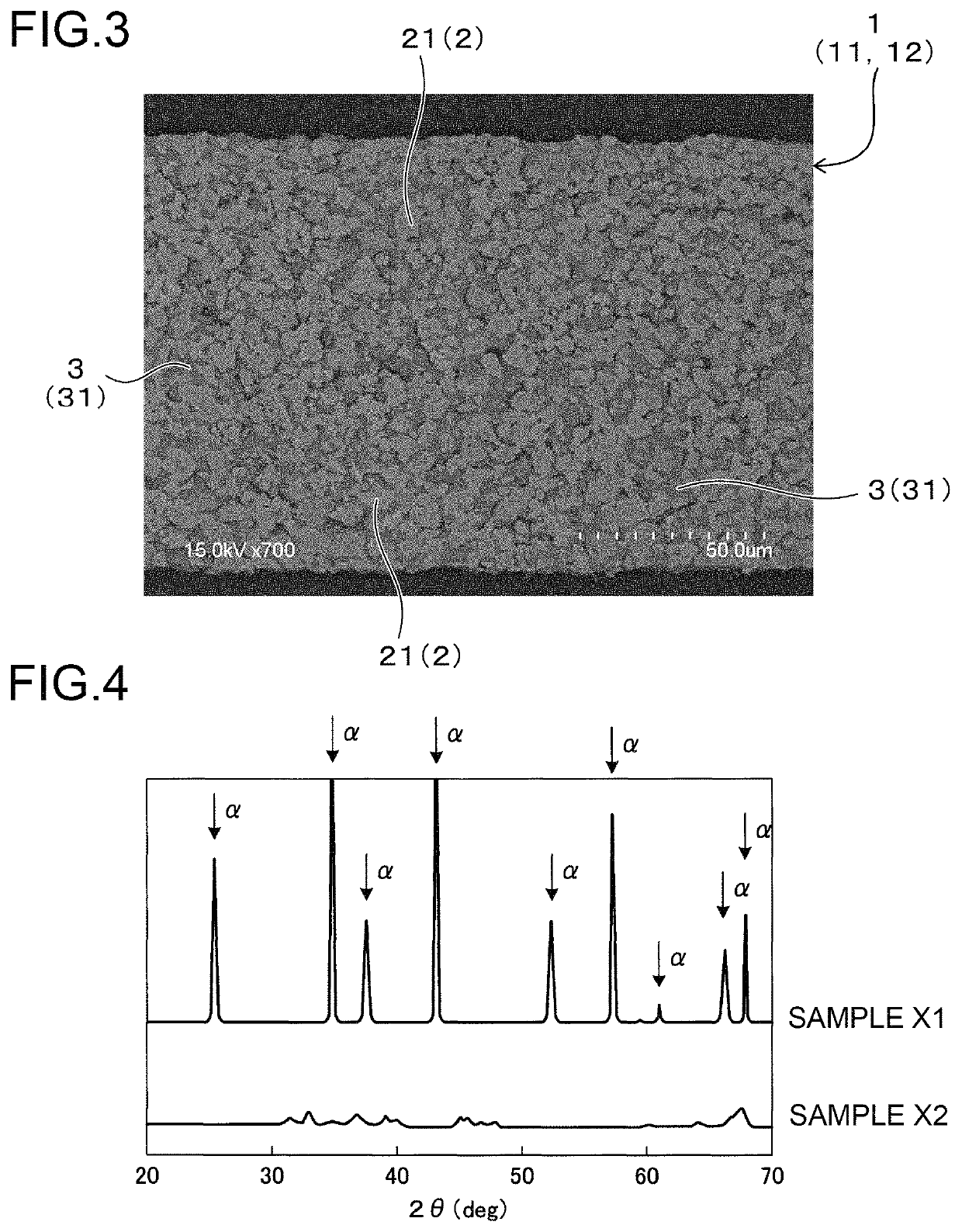
[0055]Hereinafter, a description will be given of an example of a honeycomb structure prepared by using only the first promoter particles made of a ceria-zirconia solid solution as promoter particles, without using the second promoter particles made of alumina. In a sixth example, a honeycomb structure was prepared in the same way as in the first example, except that the addition amount of the first promoter particles was changed to 100 parts by mass without using the second promoter particles and that the sintering temperature was changed to 1000° C. FIG. 3 shows an image of a cross section of the honeycomb structure of the sixth example acquired using the SEM.

[0056]As shown in FIG. 3, the honeycomb structure 1 of the sixth example included the first promoter particles 21 as the promoter particles 2, but did not include the second promoter particles 22. The first promoter particles 21 were made of a ceria-zirconia solid solution. The second promoter particles...

example

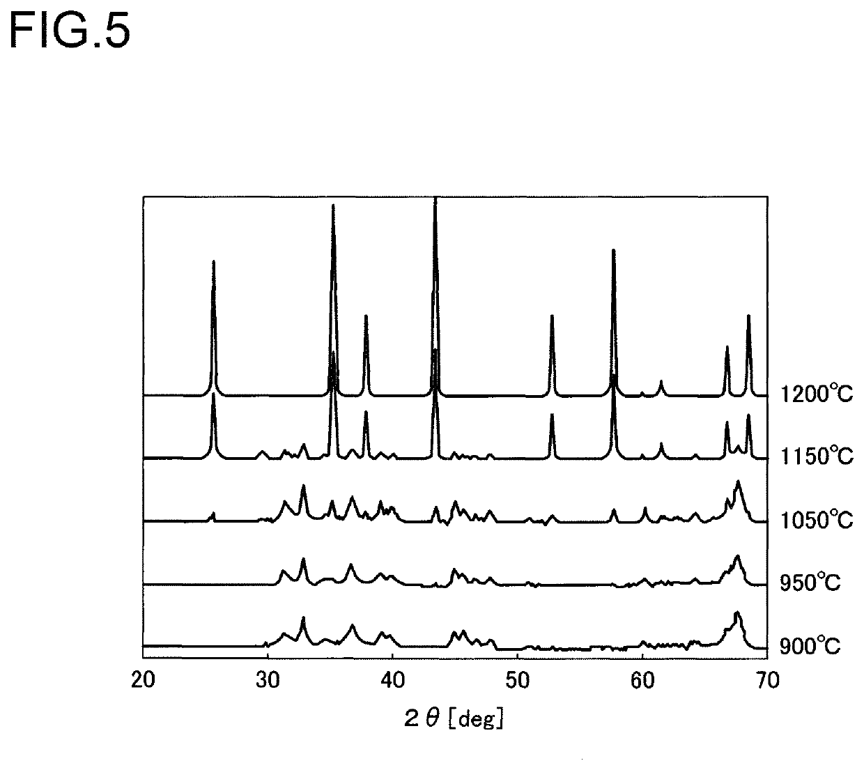
[0073]The present example is an example to examine a change of a crystal structure when an inorganic binder material made of alumina sol is sintered at different sintering temperature conditions.

[0074]A liquid mixture was prepared by mixing an inorganic binder material made of alumina sol (AS520 manufactured by Nissan Chemical Industries, Limited) with a sintering assistant solution made of an aqueous solution of an iron sulfate (II). Then, the inorganic binder materials and the sintering assistant solution were mixed so that an amount of Fe relative to 10 parts by mass in terms of solid content of alumina sol was 0.35 parts by mass in terms of oxide equivalent amount. This blending ratio was similar to the first example. Then, water in the liquid mixture was evaporated, thereby obtaining a solid. The obtained solid was sintered in an electric furnace. The sintering was performed by increasing the temperature in the electric furnace at a rate of 200° C. / h, and maintaining the temper...


PUM

PropertyMeasurementUnit
temperatureaaaaaaaaaa
diameter×Laaaaaaaaaa
thicknessaaaaaaaaaa

Abstract

The present invention relates to a honeycomb structure having promoter particles and a binder phase interposed between the promoter particles, and a method for manufacturing the same. The promoter particles contain at least first promoter particles made of a ceria-zirconia solid solution. The binder phase, in each of which a number of inorganic binder particles are aggregated with each other, with α-alumina being a main component, contain one or two of Fe and Cr dissolved in α-alumina. The honeycomb structure has a specific surface area at a ratio of 90% or more of after heating to before heating at a temperature of 1200° C.

Description

[0001]This application is the U.S. national phase of International Application No. PCT / JP2016 / 062524 filed Apr. 20, 2016 which designated the U.S. and claims priority to JP Patent Application No. 2015-116105 filed Jun. 8, 2015, the entire contents of each of which are hereby incorporated by reference.TECHNICAL FIELD[0002]This invention relates to a honeycomb structure made up of promoter particles and inorganic binder particles and to a method for manufacturing the same.BACKGROUND ART[0003]In order to purify automobile exhaust gases, honeycomb structures of conventional techniques are made of cordierite, SiC, or the like. Specifically, these honeycomb structures uses exhaust gas purifying catalysts. Such an exhaust gas purifying catalyst includes an inorganic binder carrying a promoter made of a ceria-zirconia solid solution or the like and a noble metal catalyst.[0004]Recently, honeycomb structures made of a promoter component or the like have been under development. However, when ...

Claims


Application Information

Patent Timeline
Patent Type & Authority Patents(United States)
IPC IPC(8): B01J23/83B01J23/00B01D53/94C04B35/50B01J35/04
CPCB01J35/04B01D53/945C04B35/50B01J23/002B01J23/83C04B35/488C04B2235/3217C04B2235/322C04B2235/40C04B2235/405C04B2235/448C04B2235/6562B01J23/745B01J37/08B01J23/26B01J35/30B01J35/56
Inventor KADOTA, YOUICHITAKAYAMA, YASUSHI
Owner DENSO CORP
Learn More