
Method for manufacturing flexible printed circuit board and flexible printed circuit board manufactured thereby

a manufacturing method and technology of printed circuit board, which are applied in the direction of printed element electric connection formation, conductive pattern formation, non-metallic protective coating application, etc., can solve the problems of high manufacturing cost and complicated manufacturing process, and achieve stable adhesion of circuit pattern, ensure dimensional stability, and prevent adhesion

Active Publication Date: 2019-12-17
AMOGREENTECH CO LTD
View PDF40 Cites 0 Cited by
  • Summary
  • Abstract
  • Description
  • Claims
  • Application Information

AI Technical Summary

Benefits of technology

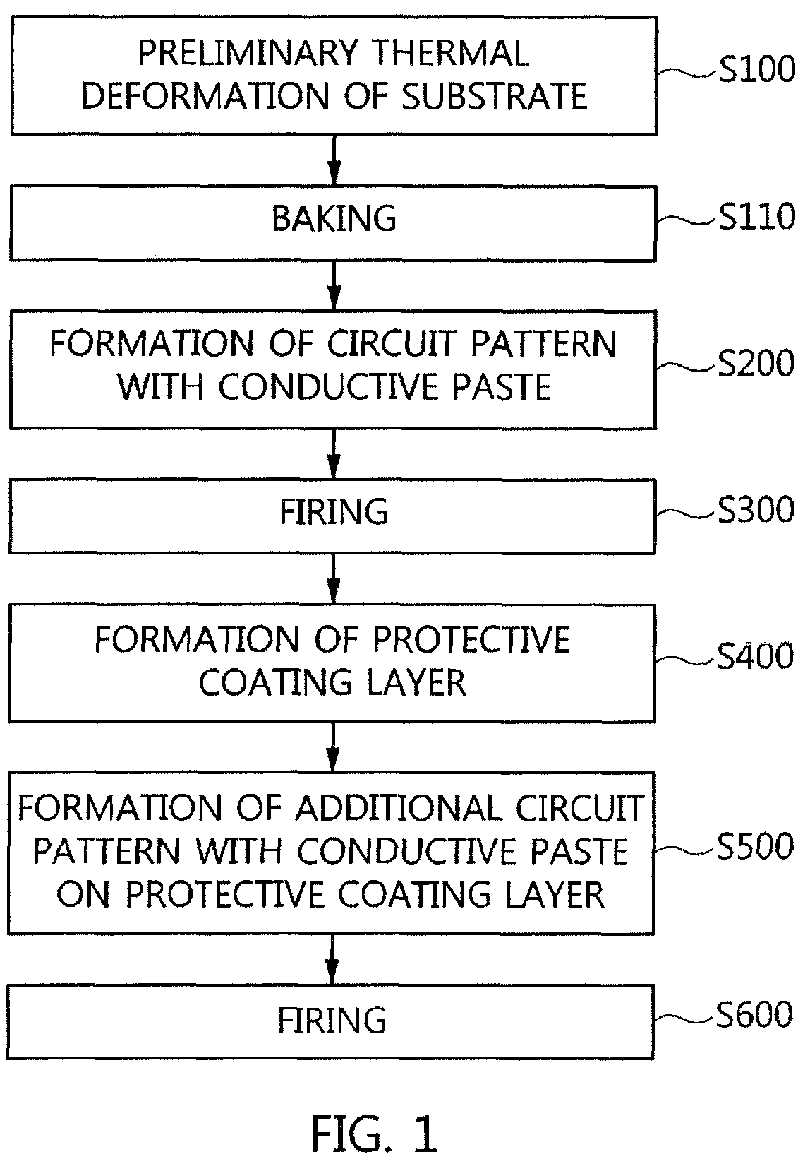
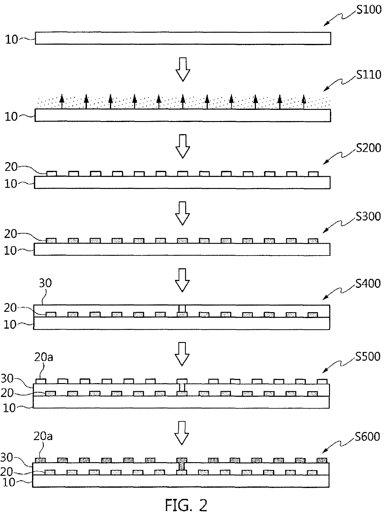
[0040]According to this disclosure, preliminary thermal treatment of a substrate can ensure dimensional stability when firing a circuit pattern printed with a conductive paste, and can also prevent adhesion between the circuit pattern and the substrate from deteriorating, which can occur due to the deformation of the film upon firing. Furthermore, stable adhesion of the circuit pattern can be maintained even after firing.
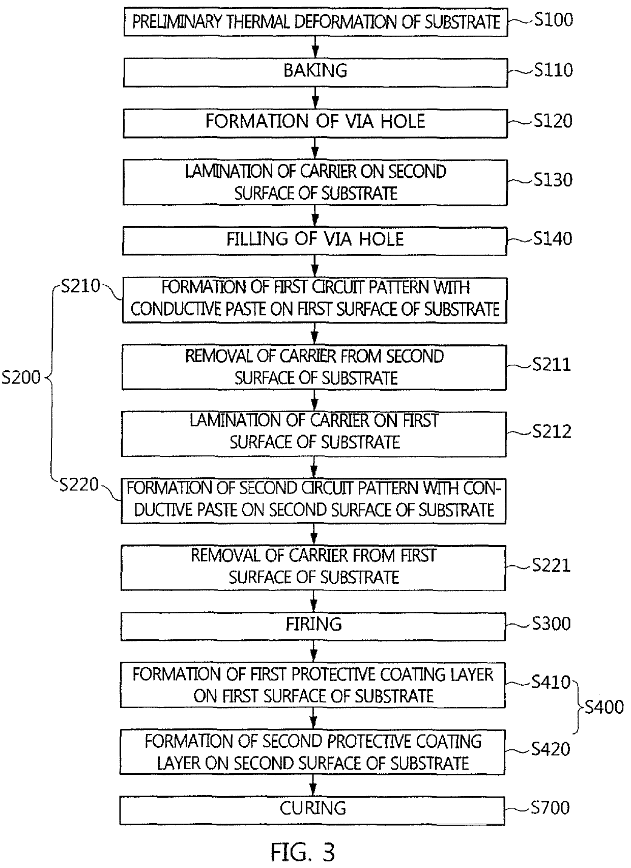
[0041]According to this disclosure, a via hole can be filled with sufficient conductive paste, thereby improving the operational reliability of the circuit pattern formed on both surfaces of the substrate.
[0042]According to the disclosure, the circuit pattern is protected by a coating layer, thereby preventing the circuit pattern from damage due to warping or bending during the use thereof and maintaining the circuit pattern firmly attached to the substrate.

Problems solved by technology

However, such flexible printed circuit boards have to undergo etching or plating, and thus suffer from complicated manufacturing processes and high manufacturing costs.

Method used


Image

  • Method for manufacturing flexible printed circuit board and flexible printed circuit board manufactured thereby
  • Method for manufacturing flexible printed circuit board and flexible printed circuit board manufactured thereby
  • Method for manufacturing flexible printed circuit board and flexible printed circuit board manufactured thereby

Examples


example 1

[0154]A silver paste comprising a silver powder having a particle size ranging from 50 nm to 5 μm and a polymer resin binder was printed on the first surface of an insulating film and the via hole and on the second surface of the insulating film and the via hole. Thereafter, the insulating film printed with the conductive paste was dried at room temperature and then thermally treated in a temperature range lower than 200° C. and in a temperature range of 300 to 450° C.

[0155]After curing and sintering of the silver paste according to the disclosure, the extent of growth of the silver powder particles was observed. Consequently, when thermal treatment (curing) was performed at a temperature of less than 200° C., the silver powder particles were in contact with each other, and when thermal treatment (sintering) was performed at 300 to 450° C., bindability between the silver powder particles was increased by the growth of the silver powder particles.

[0156]Based on the results of testing...

example 2

[0157]Thermal analysis was performed depending on the sintering temperature of the silver paste. The polymer resin binder was ethyl cellulose.

[0158]FIGS. 7 to 9 are graphs illustrating the results of thermal analysis of the silver paste according to this disclosure.

[0159]As illustrated in FIGS. 7 to 9, the thermal decomposition temperature of the polymer resin binder present in the silver paste was determined to be about 350° C., and the same results were also obtained when only the polymer resin binder was analyzed, after separation of the silver powder from the silver paste.

[0160]Therefore, when sintering was performed at 200 to 450° C., and preferably 300 to 450° C., desired adhesive strength between the insulating film and the silver paste was obtained. This is considered to be because firing was completed before thorough thermal decomposition of the polymer resin.

[0161]Based on the results of testing of FIGS. 7 to 9, interfacial separation between the insulating film and the co...

example 3

[0162]The conductive paste for pattern printing was composed of a silver powder having a particle size ranging from 200 nm to 2 μm and a polymer resin binder, and sintering was performed in the temperature range of 200 to 450° C.

[0163]Based on the results of analysis of EDX for measuring the components after sintering of the silver paste according to the disclosure, the presence of pure silver (Ag) without inorganic additives was confirmed, and the silver powder particles were grown after sintering, in which the silver powder had a spherical shape.


PUM


Abstract

A method for manufacturing a flexible printed circuit board includes preliminarily thermally deforming s substrate through heating, forming a circuit pattern with a conductive paste on the preliminarily thermally deformed substrate, and firing the circuit pattern. A flexible printed circuit board includes a substrate, and a circuit pattern formed by firing a conductive paste on a first surface of the substrate. The substrate is preliminarily thermally deformed and, thus, a shrinkage variation thereof before and after firing the conductive paste is zero. Dimensional stability when firing the circuit pattern printed with the conductive paste can be ensured, deterioration of adhesion between the circuit pattern and the substrate attributable to film deformation upon firing can be prevented, and stable adhesion of the circuit pattern can be maintained even after firing.

Description

CROSS-REFERENCE TO RELATED APPLICATIONS[0001]This application is a national phase entry under 35 U.S.C. § 371 of International Patent Application PCT / KR2014 / 003151, filed Apr. 11, 2014, designating the United States of America and published in English as International Patent Publication WO 2014 / 168451 A1 on Oct. 16, 2014, which claims the benefit under Article 8 of the Patent Cooperation Treaty and under 35 U.S.C. § 119(e) to Korean Patent Application Serial No. 10-2014-0043073, filed Apr. 10, 2014, Korean Patent Application Serial No. 10-2013-0040466, filed Apr. 12, 2013, and to Korean Patent Application Serial No. 10-2013-0040465, filed Apr. 12, 2013.TECHNICAL FIELD[0002]This disclosure relates to a method for manufacturing a flexible printed circuit board and a flexible printed circuit board manufactured thereby and, more particularly, to a flexible printed circuit board and a method for manufacturing the same, in which a circuit pattern is formed through low-temperature firing a...

Claims


Application Information

Patent Timeline
Patent Type & Authority Patents(United States)
IPC IPC(8): H05K3/46H05K3/42H05K3/12H05K3/28
CPCH05K3/1208H05K3/4664H05K3/28H05K3/0014H05K3/007H05K3/1216H05K3/1283H05K3/285H05K3/381H05K3/4069H05K2203/097H05K2203/1194H05K2203/1461H05K2203/1563H05K2203/1572
Inventor KWON, O-CHUNGYU, JEONG-SANGKIM, JAE-SICKIM, YONG-ILJANG, HYUN-SOO
Owner AMOGREENTECH CO LTD
Learn More