Method for improving the signal to noise ratio of a wave form

a waveform and signal technology, applied in the field of improving the signal to noise ratio of a waveform, can solve the problems of difficult to accurately identify or analyze the p300 signal, the noise present on the p300 response signal varies over time, and the difficulty of properly analysing, so as to improve the signal to noise ratio of the eeg signal and improve the eeg signal to noise ratio

Active Publication Date: 2020-01-07
US SEC THE ARMY THE
View PDF4 Cites 0 Cited by
  • Summary
  • Abstract
  • Description
  • Claims
  • Application Information

AI Technical Summary

Benefits of technology

[0009]The present invention provides a processor implemented method for improving the signal to noise ratio of single trial EEG signals which overcomes the disadvantages of the previously known methods and processes. Furthermore, the method of the present invention automatically adapts for different sequential time segments or time slices over the entire duration of the EEG signal.
[0014]In order to analyze the entire EEG signal, the above process is repeated for a plurality of sequential time segments or time slices. However, unlike the previously known methods to improve the signal to noise ratio of EEG signals, the wavelet coefficients for each time slice are recalculated and applied to the decomposed signal so that the method of the present invention adapts to the requirements for noise reduction of the EEG signal for each time slice over the entire period of analysis. As such, the method of the present invention is able to significantly improve the signal to noise ratio of the EEG signal despite variations of the signal and noise over the analysis period.

Problems solved by technology

One difficulty in monitoring EEG signals such as the P300 response, however, is that such signals are relatively noisy and, thus, difficult to properly analyze.
Indeed, in some situations the signal noise may obscure the P300 EEG waveforms to such a degree that it is difficult to identify or accurately analyze the P300 signal.
A disadvantage of this approach, however, is that the noise present on the P300 response signal varies over time even as short as 300 milliseconds-600 milliseconds.
Thus, while the noise filter of these previously known methods may improve the signal to noise ratio of the EEG signal over a portion of the 300-600 millisecond time period, they provide minimal, if any, improvement of the signal to noise ratio over other portions of the 300-600 millisecond P300 signal.

Method used


Image

  • Method for improving the signal to noise ratio of a wave form

Examples


Embodiment Construction

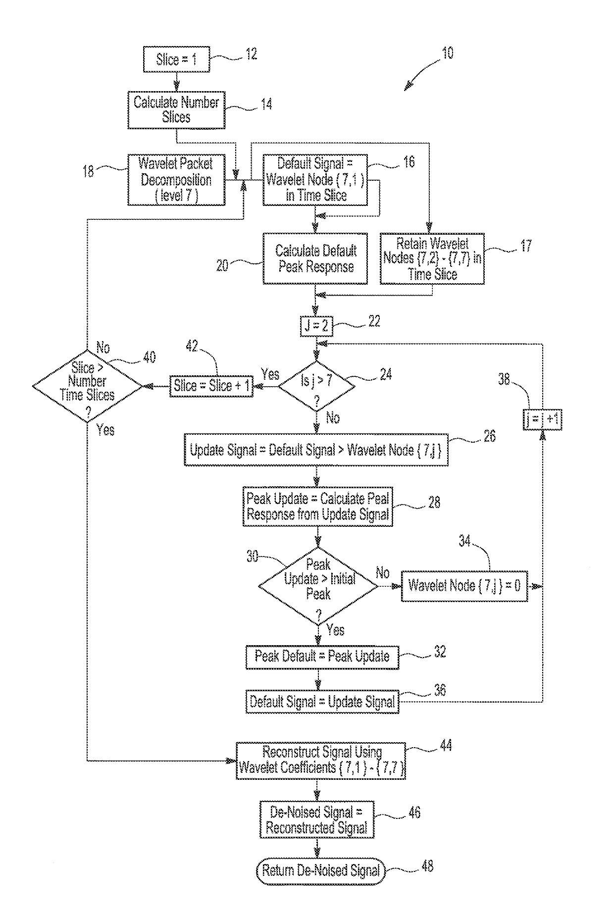
[0016]A flowchart or algorithm 10 illustrating a preferred embodiment of the method of the present invention is shown in the drawing. The flowchart 10, which will be described in greater detail, is performed by a programmed processor or programmed computer. Any conventional processor may be employed.

[0017]The method of the present invention begins at step 12 in which the time segment or time slice is set to an initial value of one. Step 12 then proceeds to step 14 where the number of time segments is calculated or set by the program. The number of time slices calculated or set at step 14 will vary depending upon the overall duration of the EEG signal to be processed by the method of the present invention. For example, a relatively large number of time slices will be set for an EEG signal of relatively long duration and vice versa. Step 14 then proceeds to step 16.

[0018]Contemporaneous with the calculation of the number of time slices, an EEG signal corresponding to the first time sl...


PUM


Abstract

A method for improving the signal to noise ratio of an EEG signal in which a wavelet packet decomposition having a plurality of levels is first applied to a time slice of the EEG signal. A default signal is set to the first wavelet packet and a default peak response is then calculated for the first wavelet node. An update signal is set to the default signal combined with another of the wavelet nodes and an update peak response signal is then calculated of the update signal. If the update peak response signal exceeds the default peak response, the default peak response is set equal to the update peak response and the default signal is set equal to the update signal. Otherwise, the value of the current node is set to zero which effectively eliminates the signal data of the current wavelet node. These steps are reiterated for all of the wavelet nodes and, thereafter, a composite waveform of the EEG signal is reconstructed from the non-zero wavelet nodes.

Description

GOVERNMENT INTEREST[0001]The embodiments described herein may be manufactured, used, and licensed by or for the United States Government without the payment of royalties thereon.BACKGROUND[0002]Technical Field[0003]The present invention relates generally to a method for improving the signal to noise ratio of a waveform and, more particularly, to a method for improving the signal to noise ratio of an EEG signal.[0004]Description of Related Art[0005]In many situations, it is desirable to monitor electroencephalography (EEG) signals. For example, hospitals and other medical facilities often utilize EEG monitors to monitor the EEG signals. Additionally, in military applications it is oftentimes desirable to monitor the EEG signals of warriors in a combat arena.[0006]It is well known that under certain circumstances, the human brain responds to certain stimuli in a manner that yields a large-amplitude response with a latency of approximately 300 milliseconds. This signal, known as the P3...

Claims


Application Information

Patent Timeline
Patent Type & Authority Patents(United States)
IPC IPC(8): A61B5/00G06K9/00A61B5/0476
CPCA61B5/7203A61B5/0476A61B5/726A61B5/369G06F2218/06A61B5/372
Inventor SIEGEL, DAVIDLY, CANHLAU, TROYHAIRSTON, WILLIAM D.
Owner US SEC THE ARMY THE
Why Eureka
Try Eureka