
Free-space optical communication links with improved sensitivity

a free-space optical communication and sensitivity technology, applied in the field of free-space optical communication systems, can solve the problems of fundamentally limited link sensitivity and inability to meet the requirements of a given application, and the cost associated with this approach is not always suitable for a given application

Active Publication Date: 2020-01-14
ANDREKSON PETER AVO +1
View PDF33 Cites 6 Cited by
  • Summary
  • Abstract
  • Description
  • Claims
  • Application Information

AI Technical Summary

Benefits of technology

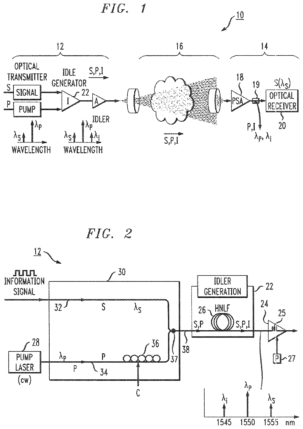
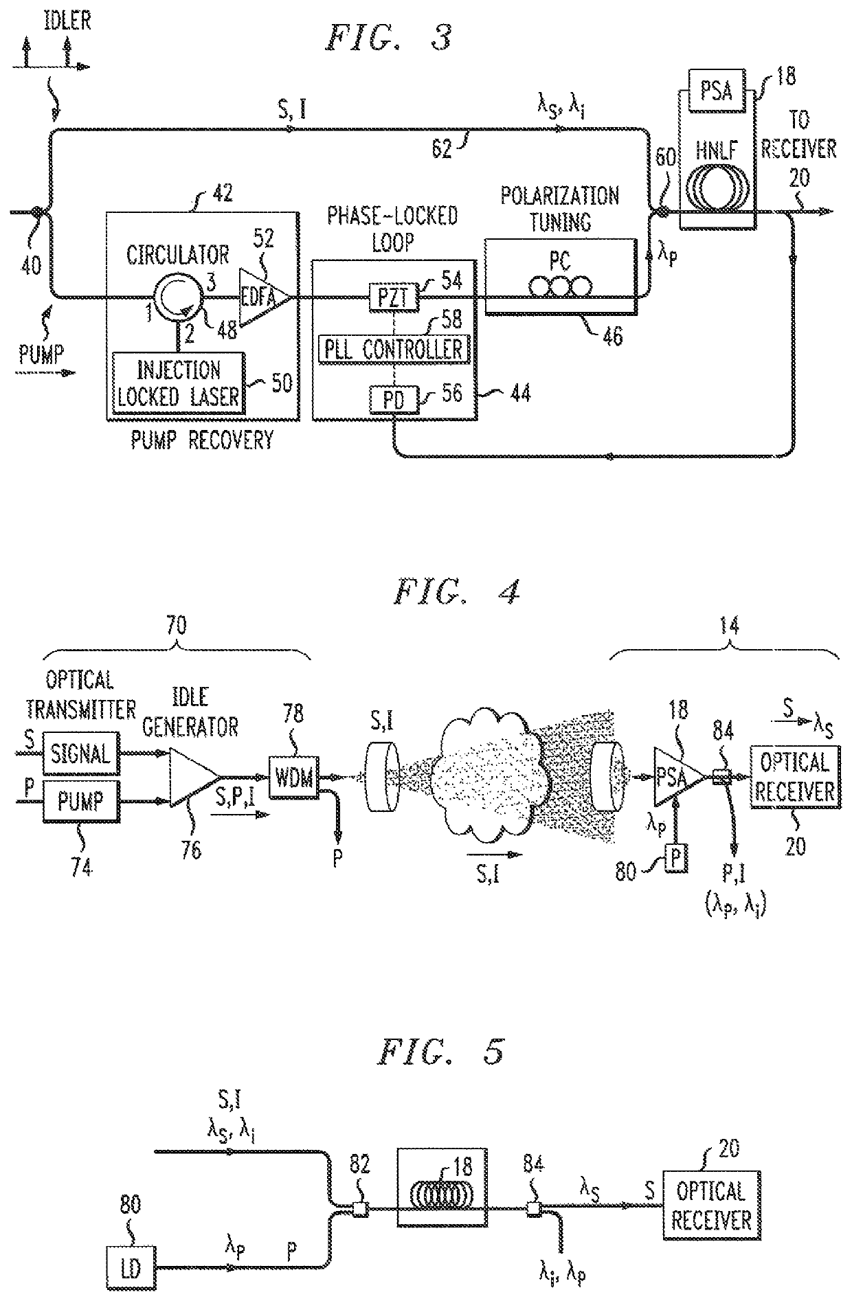
The present invention is a free-space optical communication system that uses a phase-sensitive amplifier (PSA) as a pre-amplifier at the input to the receiver portion of a free-space optical link. The PSA performs phase-sensitive amplification, relying on a nonlinear four-wave mixing (FWM) process, to amplify the received information signal. The system includes an idler generator that creates an idler signal based on the information signal and a pump wave. The idler signal is then transmitted through free space along with the original information signal. The PSA uses the idler signal as an amplification gain, which is applied to the received information signal. The technical effect of this invention is to improve the quality and stability of optical communication in free-space optical links.

Problems solved by technology

In either case of “relatively short” or “extremely long” links, the sensitivity of the link is fundamentally limited by the effects of diffraction (i.e., the continual divergence of a free-space optical beam as it travels from a transmitter to a receiver).
As there are practical limits on the size of the apertures permitted at both the transmitter and receiver, the effects of diffraction result in only a portion of the diverging beam being captured at the receiver (as a function of the aperture size / optical components at the receiver).
While improving the receiving optics allows for a larger portion of the signal to be captured, the expense associated with this approach is not always suitable for a given application.

Method used


Image

  • Free-space optical communication links with improved sensitivity
  • Free-space optical communication links with improved sensitivity

Examples


Embodiment Construction

[0019]One of the essential aspects that dictates the capacity and reach of any FSO link is the system power budget. This, in turn, depends on several metrics including, but not limited to, the launch power available at the transmitter and the sensitivity of the receiver (the latter determined as a function of the given data information bit rate and modulation format). The resulting power budget thus determines the maximum allowable loss in the transmission link—and thus also in practice the reach of the link (i.e., the distance between the transmitter and receiver).

[0020]It is proposed in accordance with the present invention to utilize a PSA in conjunction with an optical receiver in an FSO link to improve the sensitivity of the receiver. By virtue of using a PSA at the receiver input, additional margin in the overall power budget of the FSO link is provided. Inasmuch as an FSO link does not experience the types of dispersions and nonlinearities associated with fiber-based systems,...


PUM

PropertyMeasurementUnit
wavelength λsaaaaaaaaaa
wavelength λpaaaaaaaaaa

Abstract

A free-space optical communication link is proposed that utilizes phase-sensitive amplification of the received optical signal at the input to the receiver portion of the link. The transmitter component of the FSO link generates an idler signal that is transmitted through free space with the original data signal and used at the PSA in conjunction with a pump wave to impart gain onto the received information signal. The PSA performs four-wave mixing (FWM) of the data, idler and pump to create the amplified data signal. In one embodiment, the pump wave used to generate the idler at the transmitter is sent through free space with the information and idler signals and used by the PSA to perform amplification. Alternatively, the PSA may use a co-located pump laser, in combination with the received idler signal, to perform the phase-sensitive amplification process.

Description

CROSS-REFERENCE TO RELATED APPLICATIONS[0001]This application claims the benefit of U.S. Provisional Application Ser. No. 62 / 398,700, filed Sep. 23, 2016 and herein incorporated by reference.TECHNICAL FIELD[0002]The present invention relates to a free-space optical communication system and, more particularly, to the utilization of phase-sensitive amplification as a pre-amplifier at the input to the optical receiver to improve the overall performance of the free-space link.BACKGROUND OF THE INVENTION[0003]Free-space optical communication links are increasingly being used for relatively short links (e.g., about 1 km), which are often established for temporary purposes (e.g., sporting event, outdoor concert venue, and the like). By their nature, these links provide the advantages of high capacity and low latency. Free-space links are similarly being explored for extremely long links (e.g., out of the earth's orbit, between satellites, etc.). In either case of “relatively short” or “ext...

Claims


Application Information

Patent Timeline
Patent Type & Authority Patents(United States)
IPC IPC(8): H04B10/112H04B10/297H04B10/50H03F3/08G01N21/17H04B10/293H01S3/067
CPCH04B10/2971H04B10/112H04B10/1125H04B10/504H04B10/293G01N21/17H01S3/067H03F3/08
Inventor ANDREKSON, PETER AVOOLSSON, SAMUEL LARS IVAR
Owner ANDREKSON PETER AVO
Learn More