Multiplexer and method for driving the same

a technology of multiplexers and multiplexers, applied in the field of multiplexers and a method for driving the same, can solve the problems of less welcome from the consumer's perspective, significant increase in the manufacturing cost of the panels fabricated with the cmos process, etc., and achieve the effect of reducing the manufacturing process of multiplexers and/or panels, reducing the manufacturing cost of panels, and ensuring the driving capability of data lines

Active Publication Date: 2020-02-11
AU OPTRONICS CORP
View PDF2 Cites 4 Cited by
  • Summary
  • Abstract
  • Description
  • Claims
  • Application Information

AI Technical Summary

Benefits of technology

[0009]Through the embodiments of the present invention, two different reset signals are applied to the multiplexer to increase an absolute value of a voltage difference between a gate and a drain of a transistor for driving a data line, thereby strengthening the driving capability of the transistor. In this way, no matter whether the transistors of the multiplexer are NMOS transistors or PMOS transistors, the multiplexer has a sufficient driving capability for data lines and sub-pixels. Therefore, all the transistors of the multiplexer can either be N-type metal-oxide-semiconductor transistors or P-type metal-oxide-semiconductor transistors, thereby simplifying the process of manufacturing the multiplexer and / or a panel and improving the competitiveness of products thereof.

Problems solved by technology

However, compared with a circuit using purely NMOS transistors or PMOS transistors, a circuit using CMOS transistors requires a relatively complicated process and a larger number of masks, causing a significant increase in manufacturing costs of the panels fabricated with the CMOS process, which in turn is less welcome from the consumers' perspective.

Method used


Image

  • Multiplexer and method for driving the same
  • Multiplexer and method for driving the same
  • Multiplexer and method for driving the same

Examples


Embodiment Construction

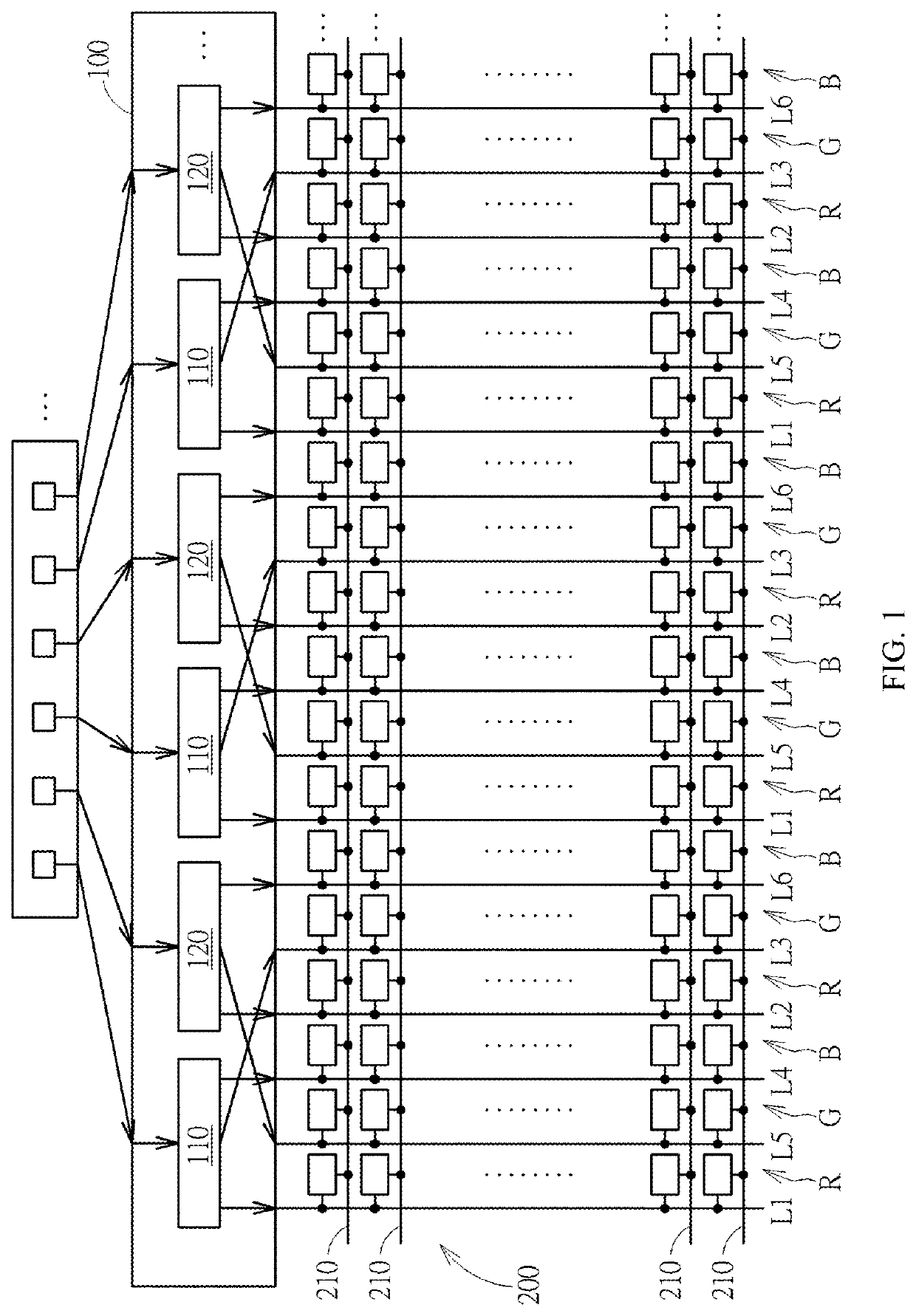
[0025]Please refer to FIG. 1. FIG. 1 is a schematic view of a multiplexer 100 applied to a display 200 according to an embodiment of the present invention. The display 200 includes the multiplexer 100, red sub-pixels R arranged in multiple columns, green sub-pixels G arranged in multiple columns, and blue sub-pixels B arranged in multiple columns, a plurality of gate lines 210, and a plurality of data lines 220. Each red sub-pixel R, each green sub-pixel G, and each blue sub-pixel B are coupled to a corresponding gate line 210 and a corresponding data line 220. The multiplexer 100 includes a plurality of driving units 110 and a plurality of driving units 120. The display 200 may be a liquid crystal display, an electroluminescent display, electrowetting display, or any other types of display.

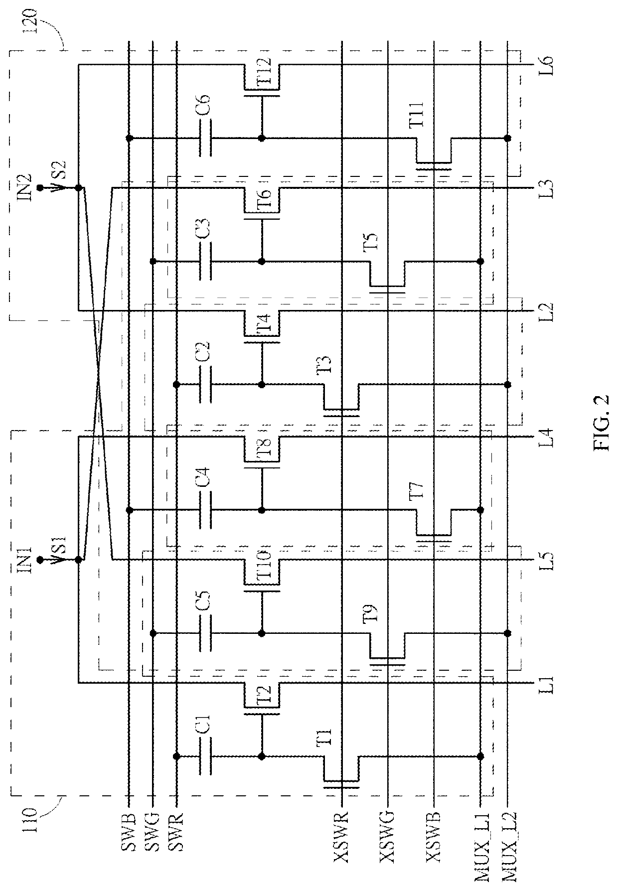
[0026]Please refer to FIG. 2. FIG. 2 is a circuit diagram of two driving units 110 and 120 for implementing the multiplexer in FIG. 1 according to an embodiment of the present invention. Each dri...


PUM


Abstract

A multiplexer is provided herein. The multiplexer has a plurality of first driving units and a plurality of second driving units. Each of the first driving units has a first data voltage input terminal, and each of the second driving units has a second data voltage input terminal. The first data voltage input terminal and the second data voltage input terminal are configured to receive pixel voltage signals with different polarities. In the first driving unit, a voltage difference between a gate and a drain of a transistor is controlled by a first reset signal, wherein the transistor of the first driving unit is coupled to the first data voltage input terminal and a first data line. In the second driving unit, a voltage difference between a gate and a drain of a transistor is controlled by a second reset signal, wherein the transistor of the second driving unit is coupled to the second data voltage input terminal and a second data line.

Description

TECHNICAL FIELD[0001]The present invention relates to a multiplexer and a method for driving the same, and specifically, to a multiplexer comprising single-type transistors and a method for driving the same.BACKGROUND ART[0002]In the current display panel technology, because a low temperature poly-silicon (LTPS) thin film transistor (TFT) has a high mobility and high reliability, the panel can have a high aperture ratio, and a circuit of a multiplexer can be formed on a substrate, so as to reduce the number of source driver ICs, and satisfy high specification panel design requirements. In addition, during the operation of the panel, because a polarity reversal operation needs to be performed on sub-pixels of the panel, the polarity of a Gamma voltage received by each of the sub-pixels in each frame period may be a positive polarity or a negative polarity. In the case where the polarity reversal operation needs to be performed on the sub-pixels, a traditional multiplexer fabricated b...

Claims


Application Information

Patent Timeline
Patent Type & Authority Patents(United States)
IPC IPC(8): G09G3/00G09G3/20G09G3/36H03K17/693G09G5/00H03K17/00
CPCG09G3/006H03K17/693G09G3/20G09G3/3614G09G5/003G09G2300/0408G09G2310/0235G09G2310/0291G09G2310/061G09G2310/0297H03K17/002G09G2300/0452G09G2310/0254G09G3/3611G09G3/3685
Inventor XI, PENG-BOSU, SUNG-YU
Owner AU OPTRONICS CORP
Why Eureka
Try Eureka