Integrated onboard chargers for plug-in electric vehicles

a technology for electric vehicles and chargers, applied in charging stations, propulsion using engine-driven generators, transportation and packaging, etc., can solve the problems of reducing the efficiency of electric vehicles, so as to achieve effective input current ripple cancellation and simple design and operation.

Active Publication Date: 2020-02-18
UNIV OF MARYLAND
View PDF7 Cites 41 Cited by
  • Summary
  • Abstract
  • Description
  • Claims
  • Application Information

AI Technical Summary

Benefits of technology

[0032]It is also an object of the present invention to provide a simple design and operational onboard battery charger integrated with the PEV's AC Propulsion machine-Propulsion Inverter Group which is (1) capable of high-power onboard battery charging with effective input current ripple cancellation, (2) does not need motor-inverter rearrangement, and (3) does not require an access to inaccessible points of the Propulsion machine's windings, and, (4) does not rotate of the Propulsion machine during steady-state charging.

Problems solved by technology

As with many options, there are advantages and disadvantages with both onboard and off-board charger systems.
The drawback with onboard chargers is the limitation in their power output due to size and weight restrictions dictated by the vehicle design.
Onboard chargers are limited in their power output only by the ability of the onboard charger to deliver the charge.
However, they contribute to additional weight, volume and cost of the car.
Due to their charging power limitations and slow charging process, it would take between 4 to 20 hours to fully charge a PEV battery using conventional level-1 and level-2 onboard chargers.
This structural approach is detrimental due to addition of extra components, weight and cost of the vehicle design.
However, to achieve all the required modes of operation, additional transistors and diodes are needed that increases the complexity and brings to the fore reliability issues.
Therefore, utilizing an integrated high-power converter as a low-power converter during relatively low-power charging prevents the attainment of high efficiency operation.
However, the proposed topologies have drawbacks in terms of requirement for bulky add-on components, customization of propulsion machines, access to inaccessible points of the propulsion machine's windings, intensive winding / inverter rearrangement, or the propulsion machine unwanted rotation during charging.
Furthermore, a DC-DC bi-directional converter 28 can be used to regulate DC_link voltage with a wide range of battery voltage variations which adds to the unwanted weight and cost of the existing onboard chargers.

Method used


Image

  • Integrated onboard chargers for plug-in electric vehicles
  • Integrated onboard chargers for plug-in electric vehicles
  • Integrated onboard chargers for plug-in electric vehicles

Examples


Embodiment Construction

)

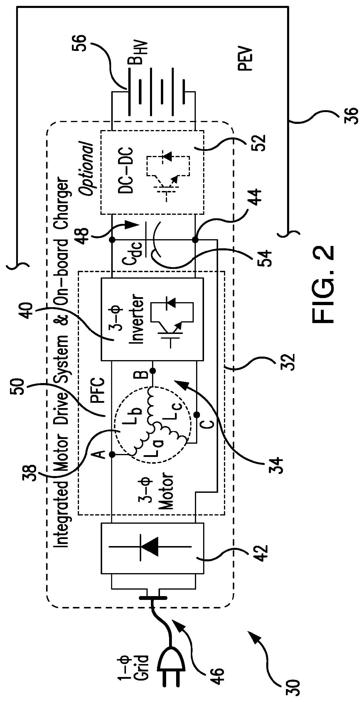
[0123]The powertrain for the plug-in electric vehicle using the subject system may include either a single high-power battery pack as the energy storage sub-system (ESS) or a number of ESSes, as well as one or a number of Propulsion machine-Inverter Groups. Each Propulsion machine-Inverter Group is built with a Propulsion Inverter followed by a Propulsion machine for electrical propulsion of the plug-in electric vehicle.

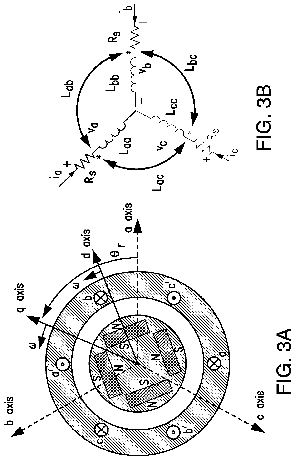
[0124]The electric propulsion is attained through at least one Propulsion machine which may include various propulsion machines, such as, for example, induction machines, permanent magnet machines, synchronous machines, switched reluctance machines, or other potential electrical machines.

[0125]The function of the Propulsion Inverters is to drive the Propulsion machine according to the speed command received from a driver. Required torque value is generated from an error between the speed command and the actual speed. Both values are supplied as inputs to a maximum e...


PUM


Abstract

An onboard charger for both single-phase (level-1 and level-2, up to 19.2 kW) and three-phase (level-3, above 20 kW) charging of a battery in Plug-in Electric Vehicles (PEVs) is integrated with the Propulsion machine-Inverter Group residing in the PEV, and is controlled to operate in propulsion and battery charging modes. The subject integrated onboard charger provides battery charging at the rated power of the Propulsion machine, does not need motor/inverter rearrangement, does not require additional bulk add-on passive components, provides an effective input current ripple cancellation, and operates without rotation of the Propulsion machine during the steady state charging.

Description

STATEMENT REGARDING FEDERAL SPONSORED RESEARCH OR DEVELOPMENT[0001]This invention was made with Government support under ECCS1238985 awarded by NSF. The Government has certain rights in the invention.REFERENCE TO THE RELATED APPLICATION(S)[0002]This Utility Patent Application is based on the Provisional Patent Application No. 62 / 237,205 filed 5 Oct. 2015.FIELD OF THE INVENTION[0003]The present invention is directed to plug-in electric vehicles (PEVs), and more in particular to onboard chargers for PEVs.[0004]In overall concept, the present invention directs itself to Level-1, Level-2 single-phase and Level-3 three-phase charging of electric vehicles using AC Propulsion machine and Propulsion inverter residing in PEVs.[0005]Additionally, the present invention is directed to an onboard charger adapted for single-phase or three-phase, as well as hybrid single- and three-phase, grid connection which is integrated with the AC Propulsion machine-Inverter group of a PEV, where the bi-direc...

Claims


Application Information

Patent Timeline
Patent Type & Authority Patents(United States)
IPC IPC(8): H02J7/00B60L53/24B60L50/10
CPCH02J7/0077B60L50/10B60L53/24B60L2210/20B60L2210/30B60L2210/10H02J7/02H02J2207/20H02J2310/48H02M1/44H02M7/797H02M1/12Y02T10/72Y02T10/70Y02T10/92Y02T10/7072Y02T90/14H02M1/007H02M3/1586
Inventor KHALIGH, ALIREZATANG, YICHAOSHI, CHUAN
Owner UNIV OF MARYLAND
Why Eureka
Try Eureka