
Control device for vehicle and control method for vehicle

a control device and vehicle technology, applied in the direction of engine-driven generators, external condition input parameters, transportation and packaging, etc., can solve the problems of poor response and driver's intention to switch, and achieve the effect of suppressing switching shock, relatively small and relatively large torque change in the first rotating machin

Active Publication Date: 2020-02-18
TOYOTA JIDOSHA KK
View PDF13 Cites 2 Cited by
  • Summary
  • Abstract
  • Description
  • Claims
  • Application Information

AI Technical Summary

Benefits of technology

This patent describes a control device and method for a vehicle that can switch between autonomous and manual driving modes. The device is designed to minimize the shock experienced during mode switching between autonomous and manual driving modes. This is achieved by adjusting the amount of torque change produced in the drive power source for traveling in response to mode switching. By doing so, the device improves the switching response during manual driving while suppressing switching shock during autonomous driving. Overall, this technology allows for seamless and safe driving experiences in both autonomous and manual modes.

Problems solved by technology

For example, if control that places an emphasis on suppression of shock is performed in the same manner during autonomous driving and during manual driving, smooth switching may be achieved during autonomous driving, but switching may be effected with poor response, against the intention of the driver, during manual driving.

Method used


Image

  • Control device for vehicle and control method for vehicle
  • Control device for vehicle and control method for vehicle
  • Control device for vehicle and control method for vehicle

Examples


first embodiment

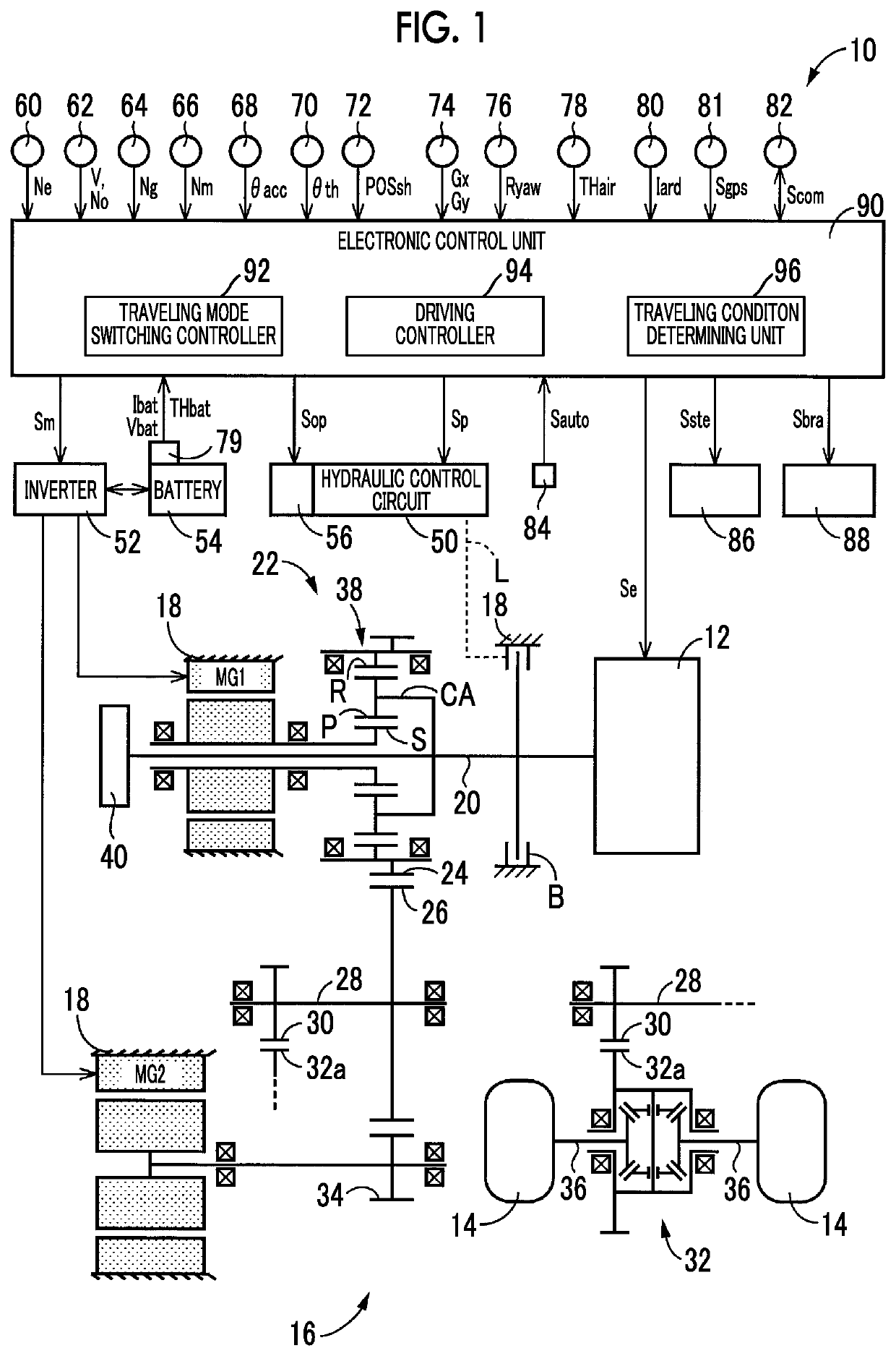
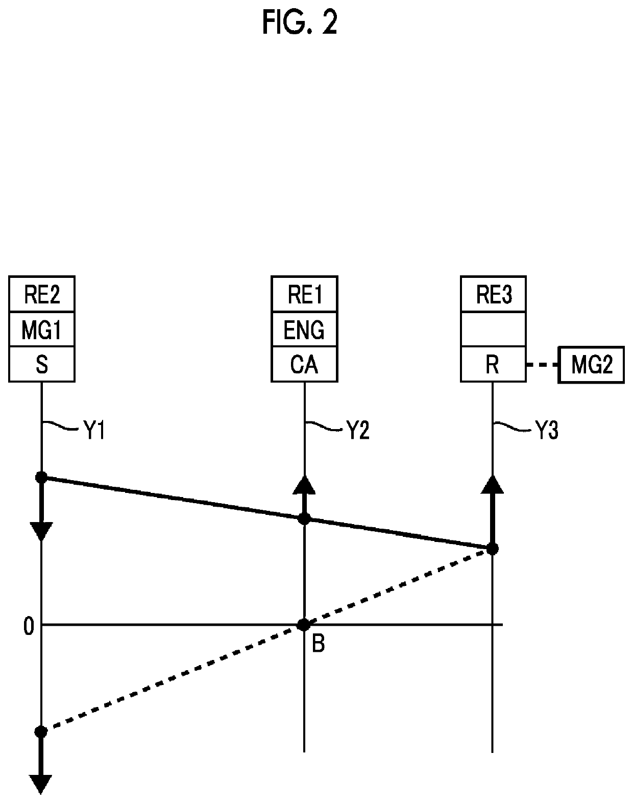
[0031]FIG. 1 shows the general configuration of a vehicle 10 to which the disclosure is applied, and also shows a principal part of a control system for controlling each part of the vehicle 10 involved in traveling. In FIG. 1, the vehicle 10 is a hybrid vehicle including an engine 12, a first rotating machine MG1, and a second rotating machine MG2, as a plurality of drive power sources, which can be drive power sources that generate drive torque and cause the vehicle to travel. The vehicle 10 also includes a power transmission unit 16 provided in a power transmission path between the engine 12 and drive wheels 14.

[0032]The engine 12 is an internal combustion engine, such as a gasoline engine or a diesel engine, which delivers power by burning certain fuel. Operating conditions, such as the throttle opening or intake air amount, fuel supply amount, and the ignition timing, of the engine 12 are controlled by an electronic control unit 90 that will be described later, so that engine to...

second embodiment

[0068]Next, a second embodiment of the disclosure will be described. In the following description, the same reference numerals are assigned to portions or components that are common to the first and second embodiments, and these portions or components will not be described in detail.

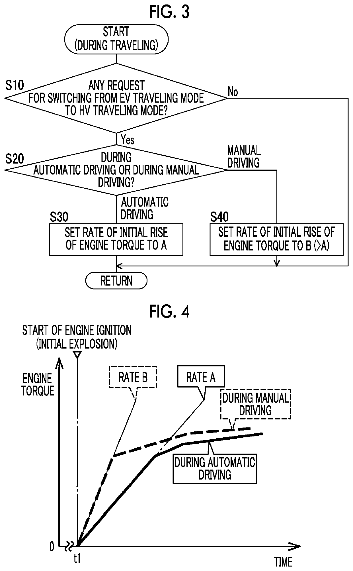
[0069]In the first embodiment as described above, the rate of initial rise of the engine torque Te during manual driving is made larger than that during autonomous driving, so that the amount of torque change produced in the engine 12 is increased. In this embodiment, when the vehicle 10 is traveling in the manual driving mode, a length of time it takes to reach a target engine torque Tetgt is set to a shorter time than that in the case where the vehicle 10 is traveling in the autonomous driving mode, so that the amount of torque change produced in the engine 12 is increased.

[0070]More specifically, if the traveling condition determining unit 96 determines that the vehicle 10 is traveling in the autonomo...

third embodiment

[0075]In this embodiment, when the traveling mode switching controller 92 switches the traveling mode according to accelerating operation of the driver during manual driving, it sets the amount of torque change (when torque is increased) produced in the drive power source for traveling subjected to switching in operation upon switching of the traveling mode, to a larger value when the amount of accelerating operation is large, than that in the case where the amount of accelerating operation is small, in addition to the first and second embodiments as described above. The accelerating operation of the driver is, for example, operation (accelerator operation) of the accelerator pedal by the driver, and its magnitude is represented by the accelerator pedal stroke θacc.

[0076]More specifically, the traveling condition determining unit 96 determines whether the accelerator pedal stroke θacc is larger than a given stroke α. The given stroke α is a predetermined threshold value based on whi...


PUM


Abstract

A control device for a vehicle includes an electronic control unit. The electronic control unit, when switching a traveling mode of the vehicle, is configured to control an amount of torque change produced in a drive power source for traveling subjected to switching in operation upon switching of the traveling mode, such that the amount of torque change during manual driving is larger than that during autonomous driving.

Description

INCORPORATION BY REFERENCE[0001]The disclosure of Japanese Patent Application No. 2016-175079 filed on Sep. 7, 2016 including the specification, drawings and abstract is incorporated herein by reference in its entirety.BACKGROUND1. Technical Field[0002]The disclosure relates to a control device for a vehicle capable of performing switching of a plurality of traveling modes, and switching between autonomous driving and manual driving, and also relates to a control method for the vehicle.2. Description of Related Art[0003]In Japanese Patent Application Publication No. 9-222922 (JP 9-222922 A), a traveling control system for a vehicle is disclosed which switches the vehicle between an autonomous driving mode under autonomous driving control, and a manual driving mode based on driving operation of a driver. The vehicle disclosed in JP 9-222922 A can be switched between the autonomous driving mode in which autonomous traveling is performed by controlling the vehicle speed and the steerin...

Claims


Application Information

Patent Timeline
Patent Type & Authority Patents(United States)
IPC IPC(8): B60W20/40B60K6/442B60K6/445B60W30/182B60W10/06B60W20/20B60W10/08B60W10/115B60W10/18B60W10/20B60W50/08B60K6/365B60K6/383B60L50/16
CPCB60W10/06B60W20/20B60W30/182B60W20/40B60W10/115B60W10/20B60K6/442B60W10/18B60W50/082B60W10/08B60K6/445B60W2710/0666Y02T10/7077Y10S903/913B60W2540/10Y02T10/6239Y02T10/7275B60W2510/242B60K6/383B60W2420/42Y02T10/6286B60W2520/14Y10S903/91B60W2510/0638Y02T10/6234B60W2756/10B60W2556/45Y10S903/93B60W2510/0604B60W2710/085B60K6/365B60W2710/0644B60W2710/083B60W2510/081B60W2710/0672B60W2540/12Y02T10/62Y02T10/72Y02T10/7072B60W60/0059B60W60/0051B60W60/0053B60W2420/403
Inventor NISHIMINE, AKIKOIMAMURA, TATSUYA
Owner TOYOTA JIDOSHA KK
Learn More