Electronic control device

a control device and electronic technology, applied in the direction of resistance/reactance/impedence, electric/magnetic position measurements, instruments, etc., can solve the problems of cross-sensitivities and corrupt measurement, and the resonance system has limitations for the conception of the inductive system, so as to achieve the effect of simple optimisation of the signal-to-noise ratio

Active Publication Date: 2020-02-25
CONTINENTAL TEVES AG & CO OHG
View PDF46 Cites 13 Cited by
  • Summary
  • Abstract
  • Description
  • Claims
  • Application Information

AI Technical Summary

Benefits of technology

By means of the apparatus that can be designed using the electronic control unit according to the invention, the measurement inductance can be measured merely using an electronic control unit in a resonant circuit. This saves energy, since the resonant circuit oscillates of its own accord and as a rule there is only a readjustment for lost energy. An enforced oscillation thus takes place. This allows use of the advantages of resonance and is free of the aforementioned restrictions of a resonant system. The use of an electronic control unit for implementing the functions saves costs and simplifies the system.
The effect achieved by the described design of an inductive system and of a combination of the components described herein is that the peak in the variables critical to the measurement, as is characteristic of resonance, can be linked in conjunction with a signal processing path, as is known from the lock-in amplifier. This decreases the current requirement of an inductive sensor system, and / or the measurement resolution thereof is increased. For the practical design of inductive sensor systems with open magnetic circuits, typical values in the range from 3 to 8 can advantageously be used or expected for Vt2 / V0.

Problems solved by technology

The resonant system has limitations for the conception of the inductive system, because only one oscillation per oscillator is possible.
Via the alteration of the oscillation frequency, cross-sensitivities can corrupt the measurement result, for example because the inductance L in addition to the sensitivity to the measured variable is influenced by a further frequency-dependent variable.
The frequency of these enforced oscillations is freely selectable, but the frequency dependency of the inductive system means that this is an inconsistency for operation at resonance, i.e. with oscillations at the natural frequency.

Method used


Image

  • Electronic control device
  • Electronic control device
  • Electronic control device

Examples


Embodiment Construction

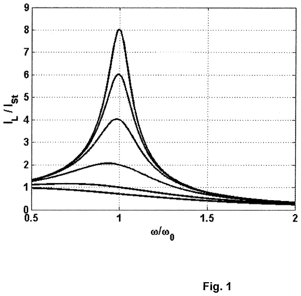
FIG. 1 has already been mentioned and explained further above in the text.

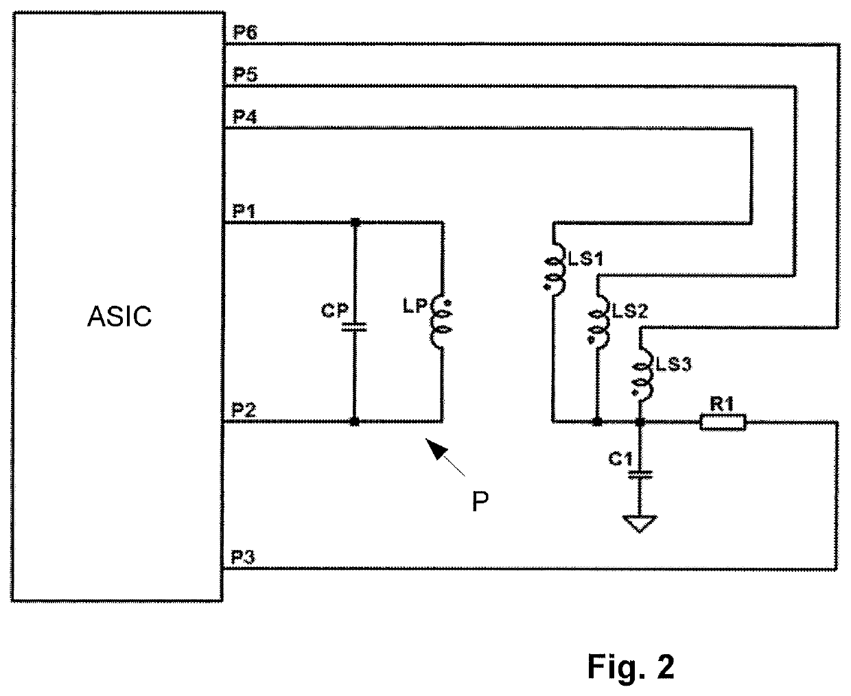
FIG. 2 shows an apparatus having an electronic control unit according to a first exemplary embodiment of the invention with an electronic control unit in the form of an application-specific integrated circuit (ASIC). In this case, an inductive system is embodied as a measurement transformer comprising a first inductance LP and three, measurement inductances, namely a first measurement inductance LS1, a second measurement inductance LS2 and a third measurement inductance LS3. A stimulus is provided by port pins P1 and P2 of the ASIC that are actuated by an internal DDS module at a provided excitation frequency or stimulus frequency.

Connected in parallel with the first inductance LP is a capacitance CP, as a result of which a parallel resonant circuit P is obtained. The oscillations of the resonant circuit P are continually maintained by alternating voltages at P1 and P2, so that an oscillation of constant ampli...


PUM


Abstract

An electronic control unit for a device for measuring a measurement variable, wherein a first inductance is supplemented by a capacitance to form a parallel resonant circuit and is excited by a micro-controller. A measuring inductance coupled to the first inductance is measured by the electronic control unit. Therefore, a measured variable can be deduced and only very few components are required in addition to the electronic control unit.

Description

CROSS REFERENCE TO RELATED APPLICATIONSThis application is the U.S. National Phase Application of PCT International Application No. PCT / EP2016 / 068158, filed Jul. 29, 2016, which claims priority to German Patent Application No. 10 2015 215 331.2, filed Aug. 11, 2015, the contents of such applications being incorporated by reference herein.FIELD OF THE INVENTIONThe invention relates to an electronic control unit for an apparatus for measuring a measured variable. In particular, such an apparatus may be an inductive sensor.BACKGROUND OF THE INVENTIONInductive sensors are typically based on a change in one or more characteristic values of a system of one or more inductive devices as a result of a measured variable. Inductive devices of this kind can refer to a coil, winding or inductance, for example.Possible characteristic values are, in particular:self inductance L, also called inductance for short,resistance loss R, which is made up of a nonreactive resistance of the winding and othe...

Claims


Application Information

Patent Timeline
Patent Type & Authority Patents(United States)
IPC IPC(8): G01D5/243G01B7/02G01B7/00G01R27/26
CPCG01B7/003G01B7/02G01R27/2611G01R27/2605G01D5/243
Inventor ACKER, HEINRICH
Owner CONTINENTAL TEVES AG & CO OHG
Why Eureka
Try Eureka