Acoustic camera and a method for revealing acoustic emissions from various locations and devices

a technology of acoustic camera and acoustic emission, which is applied in the direction of direction finders using ultrasonic/sonic/infrasonic waves, transducer types, etc., can solve the problems of reducing the usability of acoustic camera in various spaces and different measurement situations, and requiring unnecessarily large space for the housing of acoustic camera

Active Publication Date: 2020-03-10
NOISELESS ACOUSTICS OY
View PDF14 Cites 3 Cited by
  • Summary
  • Abstract
  • Description
  • Claims
  • Application Information

AI Technical Summary

Benefits of technology

[0089]The main advantage of the invention is that it allows to take an acoustic image of a larger area from a selected direction, and thus it obtains a complete view of a number of potential sound sources at once. Because the device is preferably a handheld device, it is highly maneuvreable in small spaces and difficult positions. Because the number of microphones is high, and the used calculation algorithms are efficient, the directional information of the sound sources are very accurate. The device provides good external connection possibilities. Also, the device has access to the internet, and services and analysis tools available in an external location. The rounded triangular shape of the device has the advantage that the sounds emerging from the direction of the user (behind the back of the human user pointing the acoustic camera directly in front of him / her) are well eliminated, and the focus remains in the sound sources present in front of the acoustic camera. Compared to prior art document “Benoit”, the present invention can be built in a more compact housing because the digitalization of the sound signals must be performed by a separate A / D converter, while in the present invention this is directly performed through MEMS microphones. Compared to prior art document “Kim”, the microphone arrangement in Kim is very specifically defined, while in the present invention the arrangement does not apply any branch-like structure. Also Kim requires more space in the housing of the device than the present invention, due to a separate A / D converter. Document Kim also has a separate user interface (a laptop computer) which results in more complex using of the system because it contains so many distinct operative parts. Furthermore, Kim takes the energy from the power supply mains, and thus, no internal battery is part of the device. This results in that Kim is a less mobile system while the present invention is a fully mobile system. Also the frequency range in the present invention is not as limited as in the prior art, where the prior art only applies frequencies under 20 kHz. Also the resolution and accuracy of the acoustic picture is clearly better in the present invention compared to solutions with only eight microphones.

Problems solved by technology

The main issue in Benoit is to move the microphone array (or an acoustic antenna) physically across different places of a space while the main device stays in a fixed position.
The problem of the above solutions is that many of the prior art solutions are physically quite large, and thus they require unnecessarily large space for the housing of the acoustic camera.
This further leads in more difficult handling of the acoustic camera, decreasing its usability in various spaces and different measurement situations.
Also the frequency range is very limited in some known solutions (20 Hz-20 kHz), and the resolution and accuracy of the acoustic picture is limited if there are only eight microphones in use.
Furthermore, prior art publications do not perform any classification or naming for the measured acoustic emissions.

Method used


Image

  • Acoustic camera and a method for revealing acoustic emissions from various locations and devices
  • Acoustic camera and a method for revealing acoustic emissions from various locations and devices
  • Acoustic camera and a method for revealing acoustic emissions from various locations and devices

Examples


Embodiment Construction

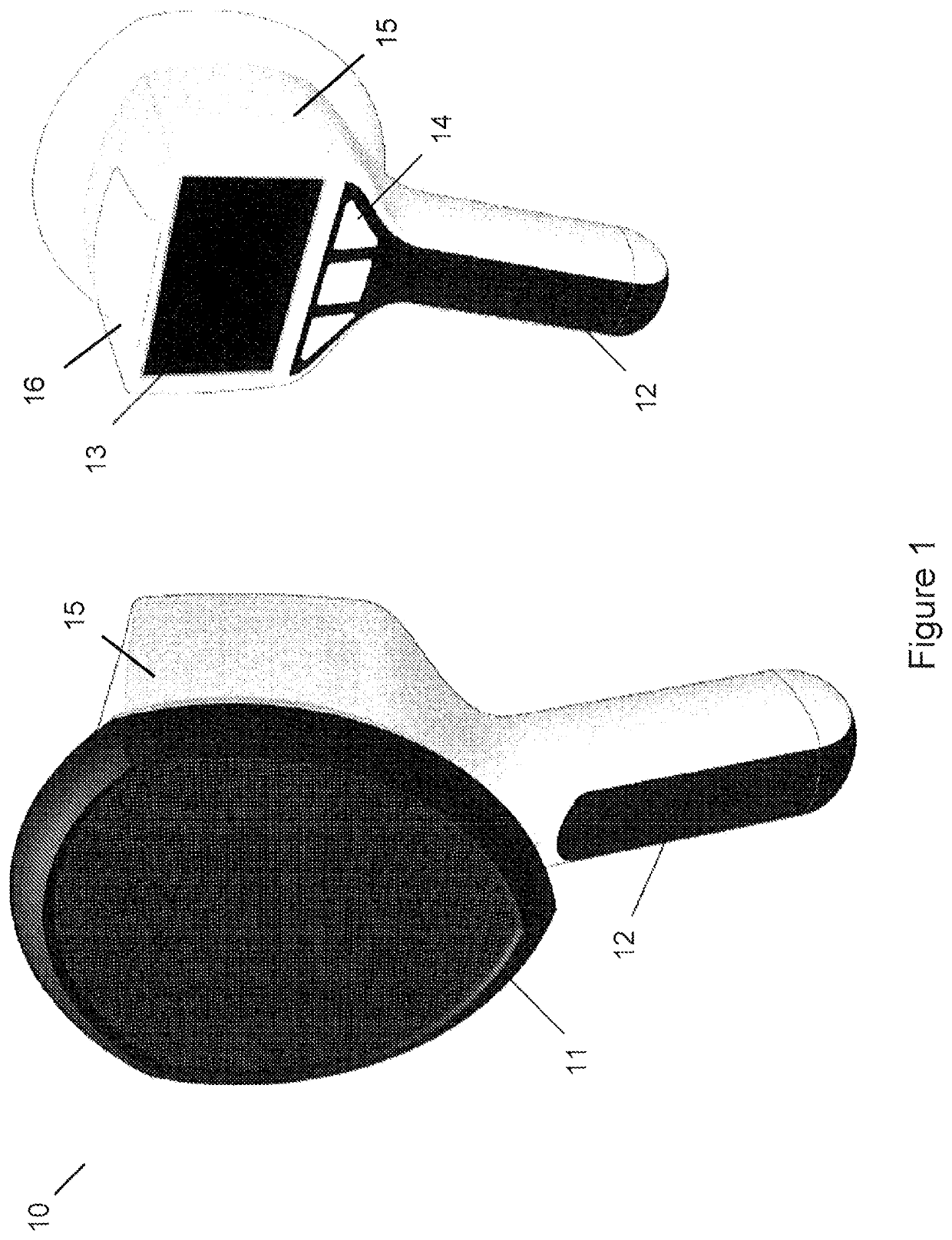
[0035]The present invention discloses an acoustic camera which is provided to analyze and present the incoming acoustic signals to the user in a sophisticated manner. In one embodiment, the acoustic camera is a handheld device and all main parts are implemented within a single housing; except a possible external loudspeaker usable as a sound source.

[0036]One embodiment of the acoustic camera and its possible outer design is illustrated in FIG. 1 from two different viewing directions. Acoustic camera 10 comprises a housing 15 which comprises the functional components in the upper part of the acoustic camera and a handle 12. The handle may comprise elastomeric material partly on its outer surface (shown in darker color). The sensing end of the housing 15 is rounded by a frame 11, which is also preferably made of an elastomeric material. The frame 11 has a rounded delta shaped form in one embodiment and the end wall of the housing 15 restricted by the frame is a planar end wall (depict...


PUM


Abstract

The present invention discloses an acoustic camera which comprises an array of arranged microphones. The microphone arrangement can be organized in planar or non-planar form. The device can be handheld, and it comprises a touch screen for interacting with the user. The acoustic camera measures acoustic signal intensities in the pointed direction and simultaneously takes an optical image of the measured area, and shows the acoustic signal strengths with the taken image on the screen. The device analyzes the acoustic signals and makes a classification for the sound based on the analysis. If necessary, an alarm is given by the acoustic camera. Besides the handheld manual use, the device can be fixed on a immobile structure or fixed to a movable or rotatable device or a vehicle, such as to a drone.

Description

PRIORITY[0001]This application is a U.S national application of the international application number PCT / FI2017 / 050631 filed on 7 Sep. 2017, which claims priority of Finnish application FI20165713 filed on Sep. 22, 2016, the contents of all of which are incorporated herein by reference.FIELD OF THE INVENTION[0002]The present invention relates to detecting acoustic emissions in various places and possible audio sources, and visualizing the detected acoustic emissions in a practical manner.BACKGROUND OF THE INVENTION[0003]Acoustic cameras are devices which collect sound signals from the environment with a microphone array, and which characterize the collected sound signals in some desired way. The acoustic camera may comprise an optical camera as well. Because the distances between each microphone and a specific sound source usually vary, the time delay differences between the received audio signals in each of the microphones can be taken into the analysis. Because the direction of th...

Claims


Application Information

Patent Timeline
Patent Type & Authority Patents(United States)
IPC IPC(8): H04R29/00H04R3/00H04R1/40H04R19/00G01H3/12G01M3/24G01S3/808
CPCH04R3/005G01H3/125H04R1/406H04R29/008G01M3/24G01S3/8083H04R2499/11H04R2201/003H04R2430/20H04R2201/401H04R2499/13H04R19/005H04R29/005G01S15/89
Inventor SAKSELA, KAINYBERG, JONAS
Owner NOISELESS ACOUSTICS OY
Why Eureka
Try Eureka