
Pre-air-filter for internal combustion engine

a technology for internal combustion engines and filters, applied in the direction of combustion-air/fuel-air treatment, filtration separation, separation processes, etc., can solve the problems of accelerating clogging, inability to achieve the intended purpose of reducing the frequency of filter replacement, etc., to achieve low melting point, improve the efficiency of filtration, and reduce the complexity of meshes in the planar direction

Active Publication Date: 2020-03-24
KUREHA LTD
View PDF21 Cites 0 Cited by
  • Summary
  • Abstract
  • Description
  • Claims
  • Application Information

AI Technical Summary

Benefits of technology

The present invention relates to a new type of nonwoven fabric that has improved water resistance and is made from a combination of a hollow crimped fiber and a low melting point fiber. The hollow crimped fiber has a hollow structure and is crimped, which increases its orientation and stiffness. The low melting point fiber is solidified and partially melted, making it easier to bind with the crimped fiber. This results in a nonwoven fabric that can hold water and prevent it from entering.

Problems solved by technology

However, a drawback in that clogging is accelerated may occur.
If the pre-air-filter is clogged soon, an intended purpose of reducing the filter replacement frequency cannot be achieved.

Method used


Image

  • Pre-air-filter for internal combustion engine
  • Pre-air-filter for internal combustion engine

Examples


example 1

[0119]As a high melting point fiber, 20% by weight of a hollow actualized crimped polyester fiber (polyethylene terephthalate (PET), melting point of 260° C., fineness of 6.6 dtex, fiber length of 51 mm, crimp degree of 20%, the number of crimps of 9 / inch, degree of hollowness of 27%), 15% by weight of a first low melting point polyester fiber (the core was PET, the sheath was modified polyester (L-PET), melting point of 110° C. glass transition temperature of 60′C, fineness of 4.4 dtex, fiber length of 51 mm), and 65% by weight of a second low melting point polyester fiber (the core was PET, the sheath was modified polyester (L-PET), melting point of 110° C., glass transition temperature of 60° C., fineness of 17 dtex, fiber length of 51 mm) were each measured, and blended, and were thereafter subjected to carding and then cross wrapping, to obtain a stacked fiber web. The stacked fiber web was needle-punched from one surface side by needles of the needle size of 40 (manufactured b...

examples 2 to 7

, Comparative Examples 1 to 2

[0120]Examples 2 to 7 and comparative examples 1 to 2 were each implemented in the same manner as in example 1 except that types and amounts of a high melting point fiber and a low melting point fiber were changed as indicated below in Tables 1 to 2, and conditions for needle punching were changed as indicated in Tables 1 to 2.

[0121]Fibers used in these production examples were as indicated below.

[0122]The “hollow actualized crimped fiber (conjugate)” is a hollow crimped fiber having a side-by-side structure, is formed from polyethylene terephthalate (PET), and has a melting point of 260° C., a fineness of 7.7 dtex, a fiber length of 51 mm, a crimp degree of 16%, the number of crimps of 8 / inch, and a degree of hollowness of 10%.

[0123]The “non-hollow fiber” is a solid crimped fiber which is formed from polyethylene terephthalate (PET), and has a melting point of 260° C., a fiber length of 51 mm, and a crimp degree, the number of crimps, and a fineness whi...


PUM

PropertyMeasurementUnit
melting pointaaaaaaaaaa

Abstract

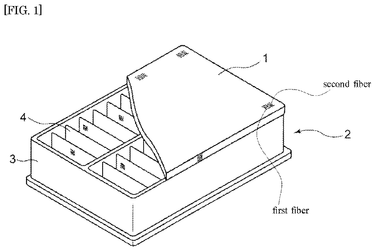
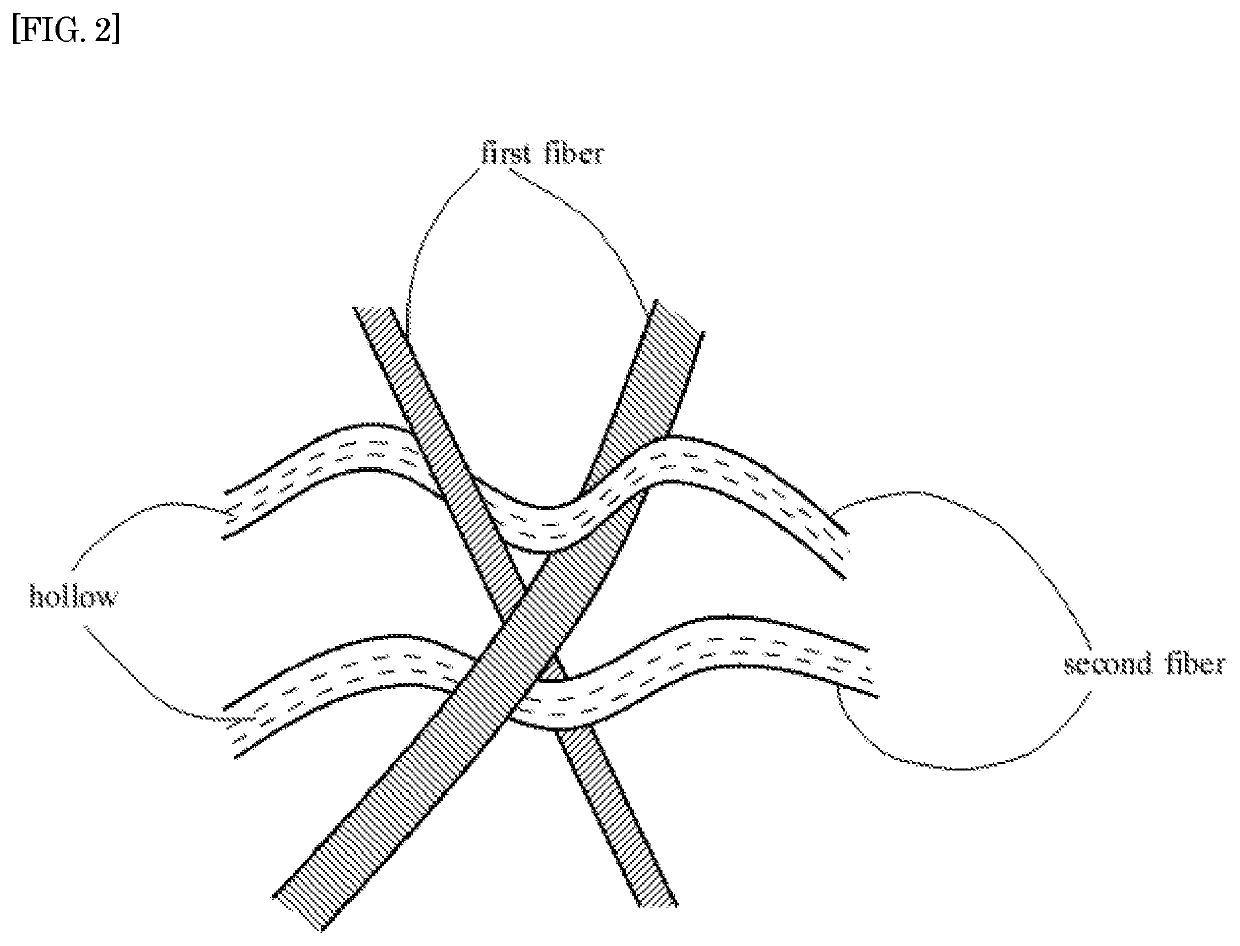
It is provided that a pre-air-filter, for an internal combustion engine, which allows stiffness to be assured even when the weight is reduced, which also has excellent dust holding properties, and which has an excellent resistance to entry of water. A pre-air-filter for an internal combustion engine (1) contains a nonwoven fabric comprising a first fiber having a melting point of not lower than 80° C. and not higher than 200° C., a second fiber having a melting point of higher than the melting point of the first fiber by not less than 30° C., being crimped, and having a hollow structure, entanglement of the first fiber and the second fiber by needle punching, and fusion of partly or entirely melted first fiber and the second fiber. This pre-air-filter (1) is installed at an air-inlet-side of a main-air-filter (2).

Description

TECHNICAL FIELD[0001]The present invention relates to a useful pre-air-filter that is formed from a nonwoven fabric and is installed on an air-inlet-side of a main-air-filter in order to enhance collection efficiency of an air cleaner used in an intake line of an internal combustion engine and an amount of dust collected by the air cleaner.BACKGROUND ART[0002]To date, a nonwoven fabric material or filter paper material has been used for an air filter of an automobile engine, and these materials are pleated to increase a filter medium area in a unit volume, thereby obtaining a predetermined dust holding capacity. For example, in a case where a nonwoven fabric material is used, although the number of pleats is small, the thickness of a filter medium is increased, and deep filtration can be thus performed, thereby obtaining a predetermined dust holding capacity. Meanwhile, in a case where a filter paper material is used, the number of pleats is increased and a filter medium area is thu...

Claims


Application Information

Patent Timeline
Patent Type & Authority Patents(United States)
IPC IPC(8): F02B77/04B01D39/16B01D46/10B01D46/12B01D46/00F02M35/02F02M35/024D04H1/4391D04H1/485D04H1/542
CPCD04H1/485F02M35/02458B01D46/10B01D39/16F02M35/024B01D46/00B01D46/0023D04H1/542B01D39/163D04H1/4391F02M35/0216B01D46/12B01D2239/0659B01D2239/1225B01D2239/064D04H1/43918D04H1/43914B01D46/62
Inventor TANAKA, KAZUMITSU
Owner KUREHA LTD
Learn More