Synchronous superconductive rotary machine having a slidable pole assembly and methods thereof

a synchronous superconducting and rotary machine technology, applied in the direction of machines/engines, efficient propulsion technologies, stator/rotor bodies, etc., can solve the problems of increasing assembly time and cost, complex and time-consuming repair process, etc., and achieve the effect of simple and easy method

Active Publication Date: 2020-03-24
ENVISION ENERGY DENMARK +1
View PDF13 Cites 0 Cited by
  • Summary
  • Abstract
  • Description
  • Claims
  • Application Information

AI Technical Summary

Benefits of technology

[0014]An object of the invention is to provide a method for assembly of a superconductive rotor in a simple and easy manner which also allows a simple and easy method of repair.DESCRIPTION OF THE INVENTION
[0083]The present invention provides a simple and easy method for replacing a defective pole unit in the rotary machine since the pole unit can be replaced without having to remove the rotor from the stator as in the conventional HTS generators.

Problems solved by technology

This solution provides a complex configuration that increases the total assembly time and costs.
However, the nuts of said bolts along with the additional bolts used to fixate the blocks are only accessible from a radial direction.
This further provides a complex and time consuming repair process as the rotor needs to be removed from the stator in the event of a repair.

Method used


Image

  • Synchronous superconductive rotary machine having a slidable pole assembly and methods thereof
  • Synchronous superconductive rotary machine having a slidable pole assembly and methods thereof
  • Synchronous superconductive rotary machine having a slidable pole assembly and methods thereof

Examples


Embodiment Construction

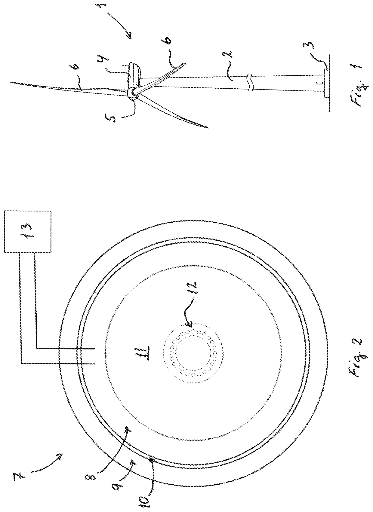
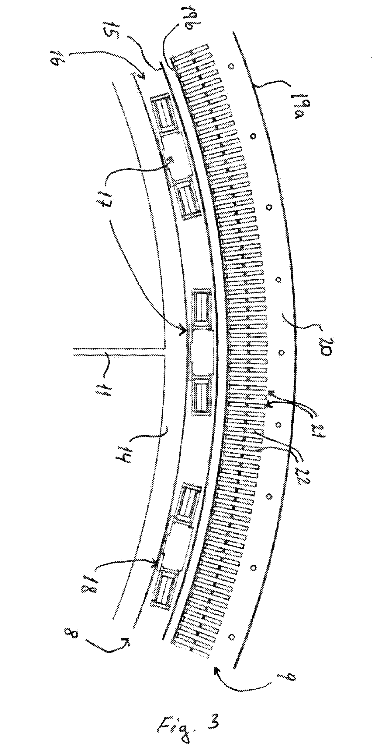
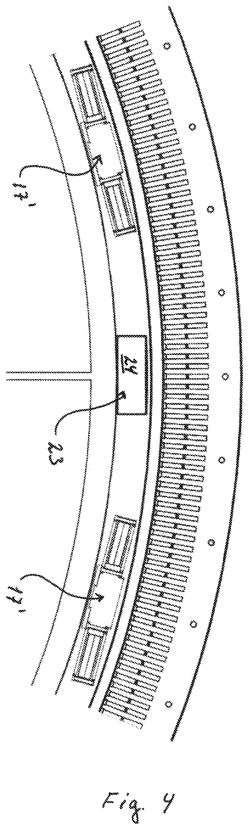
[0015]An object of the invention is achieved by a synchronous superconducting rotary machine comprising:[0016]a rotor arranged rotatably relative to a stator, wherein[0017]the rotor comprises at least a back iron configured to be connected to a drive axis, the rotor further comprises a plurality of first pole units with superconductive rotor coils, the rotor coils are configured to interact with a plurality of stator coils arranged in the stator via an electromagnetic field when the rotor is rotated relative to the stator,[0018]wherein each of the first pole units is removably connected to the back iron by means of at least one mechanical coupling comprising a first coupling element and a mating second coupling element, the first and second coupling elements extend in a longitudinal direction of the generator, wherein the first coupling element is configured to move in an axial direction relative to the second coupling element, characterised in that the rotor comprises at least one ...


PUM


Abstract

The present invention relates to a synchronous superconductive rotary machine with a superconductive rotor, a wind turbine, an assembly method and a repair method thereof. The rotor comprises a back iron connected to a thermally insulating support structure which is further connected to a base element. A coupling element is arranged on a peripheral surface of the base element for coupling to a matching coupling element located on a peripheral surface of a pole unit. The pole unit comprises a core element on which the coupling element is located and superconductive coils are wound on the core element. The pole unit is slid into position in an axial direction and fixed relative to the back iron by using fastening means. The base element, support structure and pole unit are wrapped in a thermal insulating laminate. This provides a simple and easy assembly and repair process that does require the rotor to be separated from the stator in order to replace a pole unit.

Description

[0001]This application claims the benefit of Danish Application No. PA 2014 70514 filed Aug. 28, 2014, and PCT / DK2015 / 050252 filed Aug. 28, 2015, International Publication No. WO 2016 / 029918 A1, which are hereby incorporated by reference in their entirety as if fully set forth herein.FIELD OF THE INVENTION[0002]The present invention relates to a synchronous superconducting rotary machine comprising: a rotor assembly being rotatably arranged relative to a stator assembly, wherein the rotor comprises at least a back iron configured to be connected to a drive axis, the rotor further comprises a plurality of first pole units with superconductive rotor coils, and the rotor coils are configured to interact with a plurality of stator coils arranged in the stator via an electromagnetic field when the rotor is rotated relative to the stator.[0003]The present invention also relates to a wind turbine, a method of assembling and replacing a synchronous superconducting rotary machine such as def...

Claims


Application Information

Patent Timeline
Patent Type & Authority Patents(United States)
IPC IPC(8): H02K55/04H02K15/10H02K5/128H02K9/00H02K15/02F03D9/25H02K3/52H02K7/18
CPCH02K55/04H02K5/128H02K7/1838F03D9/25H02K3/527H02K15/02H02K15/10H02K9/005Y02E10/725Y02E40/625F05B2260/20F05B2220/70642Y02T50/675F05B2260/207Y02E10/72Y02E40/60Y02T50/60H02K9/00
Inventor BÜHRER, CARSTENPÜTZ, HENDRIK
Owner ENVISION ENERGY DENMARK
Why Eureka
Try Eureka