
Frequency tunable RF filters via a wide-band SAW-multiferroic hybrid device

a wide-band saw and hybrid device technology, applied in the field of surface acoustic wave technology, can solve the problems of complex addition of bands to mobile devices, inability to adjust the frequency of fixed frequency filters, and inability to use wide-band saws

Active Publication Date: 2020-03-24
GOVERNMENT OF THE UNITED STATES AS REPRESENTED BY THE SEC OF THE AIR FORCE
View PDF23 Cites 7 Cited by
  • Summary
  • Abstract
  • Description
  • Claims
  • Application Information

AI Technical Summary

Benefits of technology

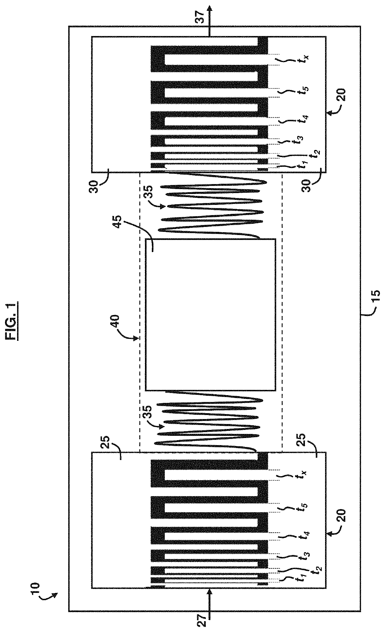
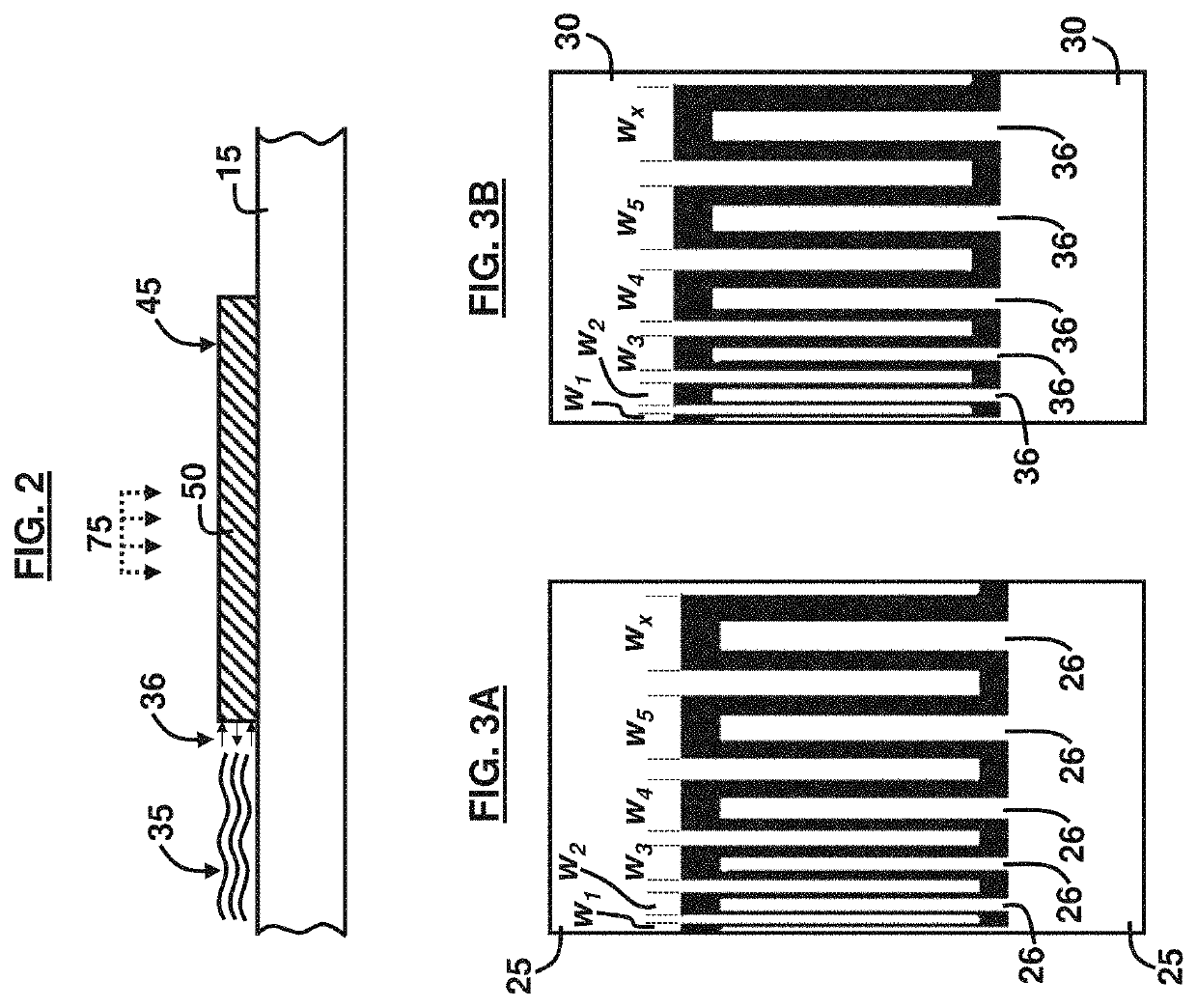
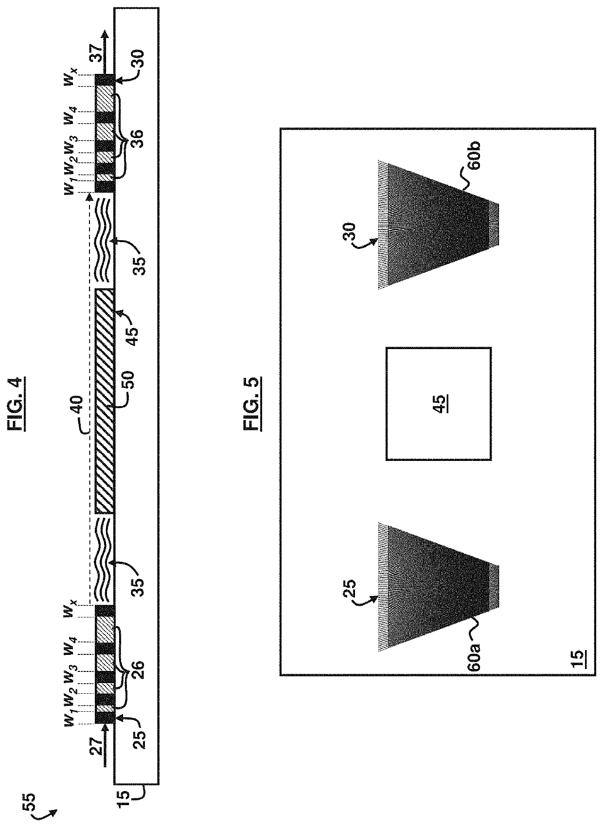
The patent describes a filter that uses a piezoelectric substrate and a SAW device to filter surface acoustic waves. The filter includes interdigitated input and output transducer electrodes with uneven widths to convert an incoming RF electrical signal into surface acoustic waves. A magnetostrictive film is positioned between the electrodes to filter the surface acoustic waves that match its resonance frequency. The filter can operate in a wide-band pass configuration and can transmit frequencies up to -60 dB. The filter can be used in a device that includes a piezoelectric substrate with first and second sets of electrodes to convert the surface acoustic waves to an electrical signal and a ferromagnetic material to filter the surface acoustic waves that match its resonance frequency. The method for tuning the filter includes applying a magnetic field or a DC voltage to induce a strain in the magnetostrictive film or the piezoelectric substrate to change the frequency of energy reflection or absorption. The filter can provide a wide-band pass and can transmit frequencies up to -60 dB.

Problems solved by technology

However, these filters tend to be fixed frequency filters without tuning capability.
Wide-band SAWS are typically not used for filtering because they do not adequately filter the frequencies.
The major issue is that adding bands to mobile devices has become complex and cost inefficient.
However, achieving these results has not been achieved in the SAW filtering industry.
The disadvantages of these filters include slow response (e.g., on the order of seconds) and having a large size (e.g., approximately 330 in3).
One disadvantage is a relatively low isolation and selectivity.
These can be improved through using multiple filters, but at the cost of insertion loss (e.g., the loss of signal power resulting from the insertion of a device in a transmission line).
While this equation describes the response for a simple isotropic ferromagnet, in the case of anisotropy, the relationship between frequency and field becomes more complicated.
The major disadvantage of these filters is their power consumption which is 100's of milliamps to amps to hold the full range tuned value.
Nonetheless, there is not good tunable replacement to acoustic filters in mobile systems.
For example, frequency tunable filtering can be accomplished through software defined approaches, but unfortunately these methods can be computationally costly.
Creating a “tunable filter” from filter banks that switch between a large array of narrow-band fixed filters is possible, but unfortunately the size, cost and losses associated with switches / interconnects makes this approach undesirable.
MEMs resonators have also been a proposed solution, but unfortunately these devices suffer from very high impedance and very low tuning at microwave frequencies.
Tunable acoustic wave filters have also been proposed, but unfortunately the acoustic velocity and / or the dimensional changes are generally much too small to make a good filter.

Method used


Image

  • Frequency tunable RF filters via a wide-band SAW-multiferroic hybrid device
  • Frequency tunable RF filters via a wide-band SAW-multiferroic hybrid device
  • Frequency tunable RF filters via a wide-band SAW-multiferroic hybrid device

Examples


Embodiment Construction

[0045]Embodiments of the disclosed invention, its various features and the advantageous details thereof, are explained more fully with reference to the non-limiting embodiments that are illustrated in the accompanying drawings and detailed in the following description. Descriptions of well-known components and processing techniques are omitted to not unnecessarily obscure what is being disclosed. Examples may be provided and when so provided are intended merely to facilitate an understanding of the ways in which the invention may be practiced and to further enable those of skill in the art to practice its various embodiments. Accordingly, examples should not be construed as limiting the scope of what is disclosed and otherwise claimed.

[0046]In the drawings, the size and relative sizes of layers and regions may be exaggerated for clarity. The embodiments herein provide a combination of a SAW device that acts as a transmitter and a magnetic material / film that acts as a filter. The emb...


PUM


Abstract

A filter including a piezoelectric substrate; a surface acoustic wave (SAW) device on the piezoelectric substrate and including unequally spaced interdigitated input and output transducer electrodes of unequal widths, wherein the input transducer electrodes are to convert an incoming radio frequency (RF) electrical signal into surface acoustic waves; a SAW propagation path between the input and output transducer electrodes; and a magnetostrictive film in the SAW propagation path to filter the surface acoustic waves that are at a ferromagnetic resonance frequency of the magnetostrictive film, wherein the output transducer electrodes are to convert the filtered surface acoustic waves into an outgoing electrical RF signal. The SAW device may operate in a wide-band pass configuration. The wide-band pass configuration result in a transmission of frequencies up to −60 dB. The magnetostrictive film may include a ferromagnetic material. The interdigitated input and output transducer electrodes may include unequal widths between adjacent electrodes.

Description

CROSS-REFERENCE TO RELATED APPLICATION(S)[0001]This application claims the benefit of U.S. Provisional Patent Application No. 62 / 555,407 filed on Sep. 7, 2017, which is incorporated herein by reference in its entirety.GOVERNMENT INTEREST[0002]The invention described herein may be manufactured and used by or for the Government of the United States for all government purposes without the payment of any royalty.BACKGROUNDField of the Invention[0003]The embodiments herein generally relate to surface acoustic wave technologies, and more particularly filters using surface acoustic waves.Background of the Invention[0004]Currently cell phones use frequency static surface acoustic wave (SAW) and bulk acoustic wave (BAW) filters combined together in ladder-like geometries to achieve the needed filtering requirements. These filter banks have several discreet filtering profiles. A typical SAW filter contains electrodes arranged in a comb-like configuration that convert electric signals into sur...

Claims


Application Information

Patent Timeline
IPC IPC(8): H03H9/64H03H9/145H03H9/22H03H9/02H03H9/42
CPCH03H9/0296H03H9/643H03H9/426H03H9/14555H03H9/1457H03H9/14514H03H9/14547H03H9/22H03H9/64H03H2210/012H03H9/14558H03H2009/02165H03H2240/00
Inventor MCCONNEY, MICHAEL E.HOWE, BRANDON M.SHAH, PIYUSHPAGE, MICHAEL R.
Owner GOVERNMENT OF THE UNITED STATES AS REPRESENTED BY THE SEC OF THE AIR FORCE
Learn More