Shielded power coupling device

a shielded power and coupling technology, applied in applications, tomography, transportation and packaging, etc., can solve the problems of reducing power transfer efficiency, increasing leakage inductance, and/or reducing the efficiency of faraday cages, etc., to eliminate or minimize the formation of virtual current loops.

Active Publication Date: 2020-03-31
ANLOGIC CORP (US)
View PDF138 Cites 0 Cited by
  • Summary
  • Abstract
  • Description
  • Claims
  • Application Information

AI Technical Summary

Benefits of technology

[0009]It is furthermore preferred that arrangement of windings 110, 160 and / or distribution of reluctance-lowering material at core regions 115, 165 be such as to align magnetic flux such that magnetic flux loops lie in meridional planes, e.g., planes of minor circle(s) where the overall axisymmetric structure is more or less toroidal. It is furthermore preferred in one or more embodiments of the present invention that E-cores or the like having multiple core recesses be employed so as to permit a net instantaneous current in the primary windings of substantially zero (i.e., such that respective magnetization currents at respective primary windings mutually cancel). It is furthermore preferred, especially where core region(s) 115, 165 comprise a multiplicity of core segments, that there be minimal interruption to axisymmetry, e.g., due to arrangement, including spacing, of core segments, or due to manner in which winding lead wire(s) enter and / or exit core recess(es); e.g., passageway(s) are preferably employed. It is furthermore preferred that winding lead wire(s), for example, pass through core(s) in such fashion and at such location(s) as will substantially eliminate or minimize formation of virtual current loop(s).

Problems solved by technology

Lack of adequate shielding may, for example, result in undesirable RF emission, increased leakage inductance, and / or reduced power transfer efficiency.
Moreover, where power is being transferred between or among bodies capable of engaging in relative rotation, it may be impossible or impractical to employ an unbroken Faraday cage or other such integral shield that would completely surround the power coupling device, it being instead necessary to employ a shield that only partially encloses the power coupling device or to divide such shield into multiple parts split so as to form gap(s) permitting relative rotation between or among such bodies.

Method used


Image

  • Shielded power coupling device
  • Shielded power coupling device
  • Shielded power coupling device

Examples


Embodiment Construction

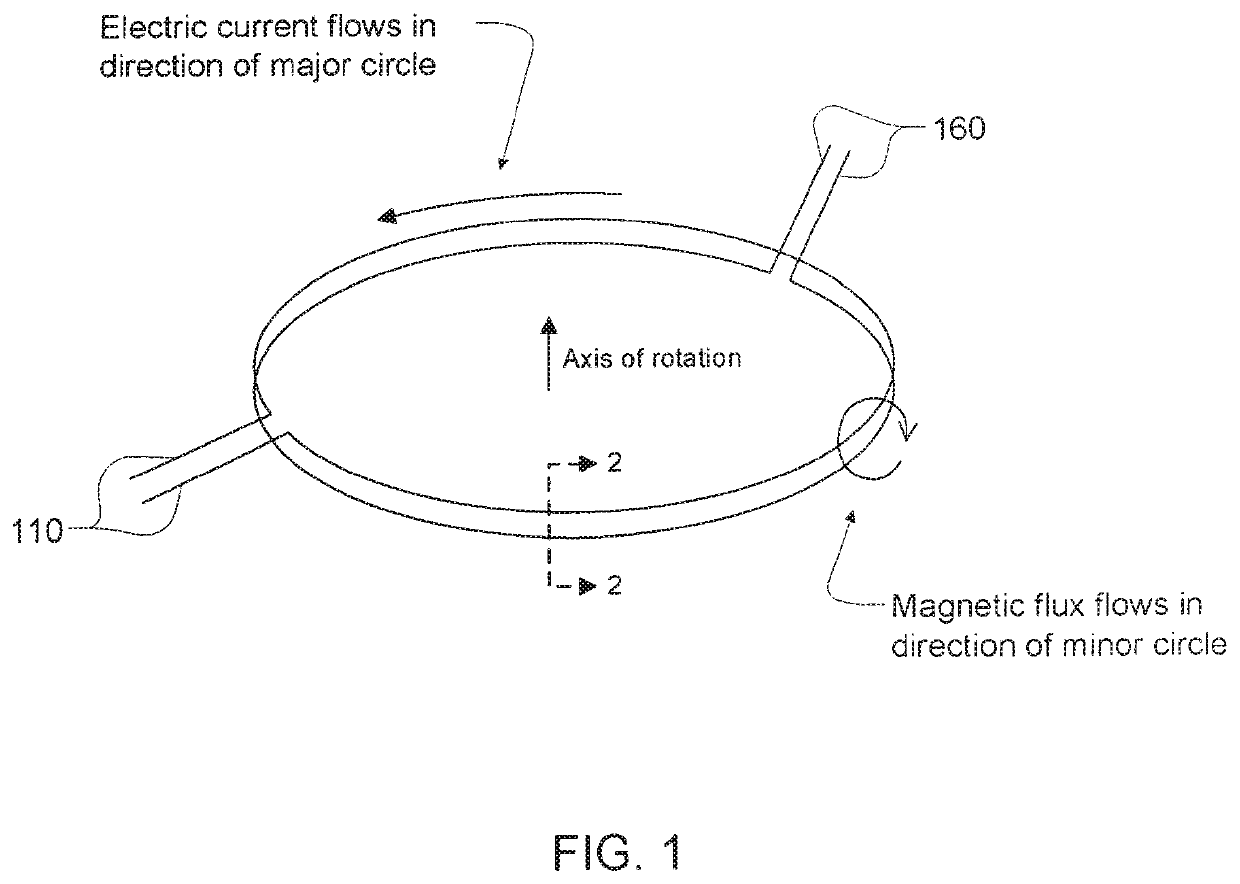
[0034]The present disclosure relates to a shielded power coupling device; more particularly, to a shielded power coupling device capable of reducing RF emission and / or other electromagnetic interference, reducing leakage inductance, and / or improving efficiency during inductive transfer of electric power in the context, for example, of a computed tomography (CT) scanner such as might be used in medical or security applications or the like, or in the context of other such applications where transfer of electric power between or among bodies capable of engaging in relative rotation is desired.

[0035]As used herein, the terms “electromagnetic interference,”“radio frequency (RF) emission,” and the like can in their most general senses include interference from surrounding equipment as it affects operation of power coupling device(s) in accordance with embodiment(s) of the present invention, but such terms are especially intended to refer to interference generated by power coupling device(...


PUM

PropertyMeasurementUnit
transfer poweraaaaaaaaaa
poweraaaaaaaaaa
frequenciesaaaaaaaaaa

Abstract

Axisymmetric solid of revolution derivable from section at FIG. 5 is generally toroidal with electric current(s) in windings preferably flowing circumferentially along major circle(s) during power coupling device operation. Current(s) in windings, current(s) in half-shields, and the volume of space swept out by shield airgap(s) emerge from plane of paper perpendicularly at FIG. 5, but as these emerge therefrom, they curve to follow toroidal major circle(s). Core regions preferably shunt and align magnetic flux such that magnetic field lines escape therefrom primarily only in region(s) of core airgap(s) and such that magnetic flux loops lie in planes of toroidal minor circle(s). Half-shield(s) preferably have electrically conductive material(s) distributed therein as is sufficient to substantially cancel magnetic flux lines impinging thereon before effects of such impinging magnetic flux lines would reach shield airgap(s) and/or outer surface(s) of half-shields.

Description

CROSS-REFERENCE TO RELATED APPLICATIONS[0001]This application claims priority to and is a continuation of U.S. patent application Ser. No. 13 / 719,935, titled “SHIELDED POWER COUPLING DEVICE” and filed on Dec. 19, 2012, now U.S. Pat. No. 9,490,063, issued Nov. 8, 2016 which is a continuation of U.S. patent application Ser. No. 11 / 699,529, titled “SHIELDED POWER COUPLING DEVICE” and filed on Jan. 29, 2007, now U.S. Pat. No. 8,350,655 issued Jan. 8, 2013, which is a continuation-in-part of U.S. patent application Ser. No. 10 / 787,270, titled “POWER COUPLING DEVICE” and filed on Feb. 26, 2004, now U.S. Pat. No. 7,868,723 issued Jan. 11, 2011, which claims priority to U.S. Provisional Application No. 60 / 450,038, titled “NON-CONTACTING POWER COUPLING DEVICE” and filed on Feb. 26, 2003. Application Ser. Nos. 13 / 719,935, 11 / 699,529, 10 / 787,270 and 60 / 450,038 are incorporated herein by reference.TECHNICAL FIELD[0002]The present disclosure relates to a shielded power coupling device; more part...

Claims


Application Information

Patent Timeline
Patent Type & Authority Patents(United States)
IPC IPC(8): H01F38/18A61B6/03A61B6/00H01F30/06H01F27/36H02J50/70H01F30/16H02J50/10H02J7/00
CPCH02J50/10H02J50/70H02J7/0042H01F38/18H01F30/16H01F27/367A61B6/032H01F30/06A61B6/56H01F27/36H01F27/363H02J2310/23
Inventor DOBBS, JOHN
Owner ANLOGIC CORP (US)
Why Eureka
Try Eureka