
Compressor systems for use with smokeless lubricant

a smokeless lubricant and compressor technology, applied in the direction of liquid fuel engines, lighting and heating apparatus, separation processes, etc., can solve the problems of aerosol formation, add to the cost of operation, aerosol formation is not readily available, etc., to reduce the efficiency of heat exchangers, minimize or eliminate the likelihood, the effect of reducing the formation of oil aerosols

Inactive Publication Date: 2005-04-19
YORK INT CORP
View PDF17 Cites 8 Cited by
  • Summary
  • Abstract
  • Description
  • Claims
  • Application Information

AI Technical Summary

Benefits of technology

The implementation of smokeless lubricants significantly reduces the number of fine lubricant particles in the gas stream, minimizing pressure drop and enhancing overall compressor system efficiency, allowing for a smaller separator design and reduced maintenance costs.

Problems solved by technology

However, for larger reciprocating compressors, lubrication loss can present a problem.
These aerosols do not readily coalesce and are not readily removable from the fluid stream without inclusion of special aerosol-removing equipment such as coalescers, which is a part of a separator portion of a compressor system.
Of course, this requires additional lubricant in the system to accommodate the volume of lubricant that is always absent from the compressor, which adds to the cost of operation since lubricant is expensive.
Furthermore, the presence of the lubricant in other parts of a closed system can lead to the downstream equipment not operating efficiently.
If a sufficient volume of oil is removed from the compressor, the compressor undesirably can be depleted of oil.
While these designs are effective in agglomerating the oil and minimizing the loss of oil to the chiller system, the compressed fluid undergoes a pressure loss as the mixture of aerosol, which resembles a smoke, passes through the coalescing device.
This pressure loss is directly related to system performance, reducing the efficiency of the unit.
However, in most applications, space is a consideration, and the separator occupies space that could be otherwise utilized.
However, this gasketed joint undesirably provides a potential leak path.
A further disadvantage is the additional cost associated with manufacturing the structures that house the coalescer element.
While these lubricants have been proposed for use with compressor systems, none of the lubricants has found commercial application for use with refrigerants typically used in compressor systems.
These lubricants also tend to be more expensive, and their use in existing positive-displacement type compressor systems, such as screw compressor systems have provided no distinct advantages to justify their increased cost.
However, the patents do not recognize system improvements that can be engineered as a result of the use of such lubricants.
With each surface that the fluid contacts, there is some energy loss and some coalescence of the lubricant droplets across the size spectrum of droplets.
However, none of the prior art discloses the advantages that can be realized in the chiller systems by incorporation of the smokeless-type oils into the chiller systems.

Method used


Image

  • Compressor systems for use with smokeless lubricant
  • Compressor systems for use with smokeless lubricant
  • Compressor systems for use with smokeless lubricant

Examples


example 1

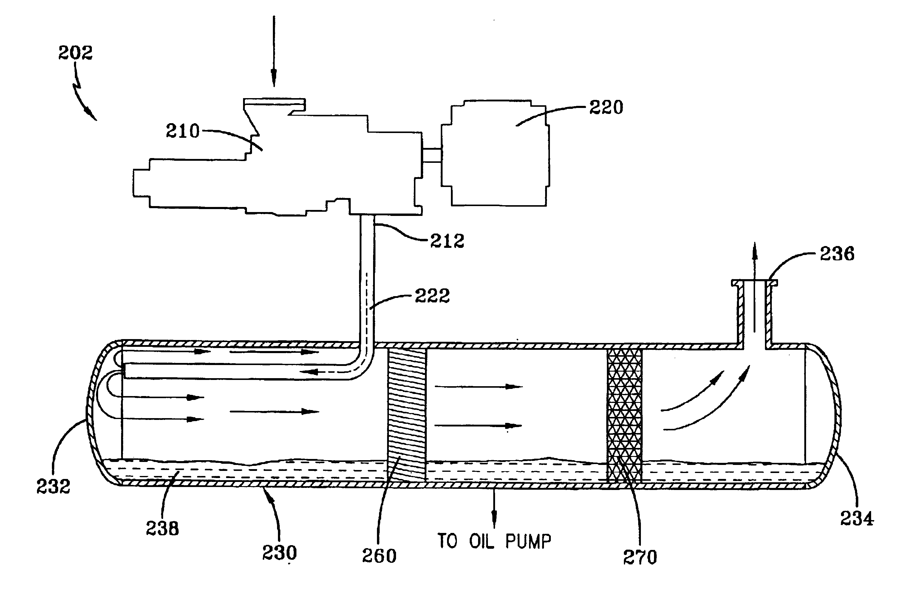
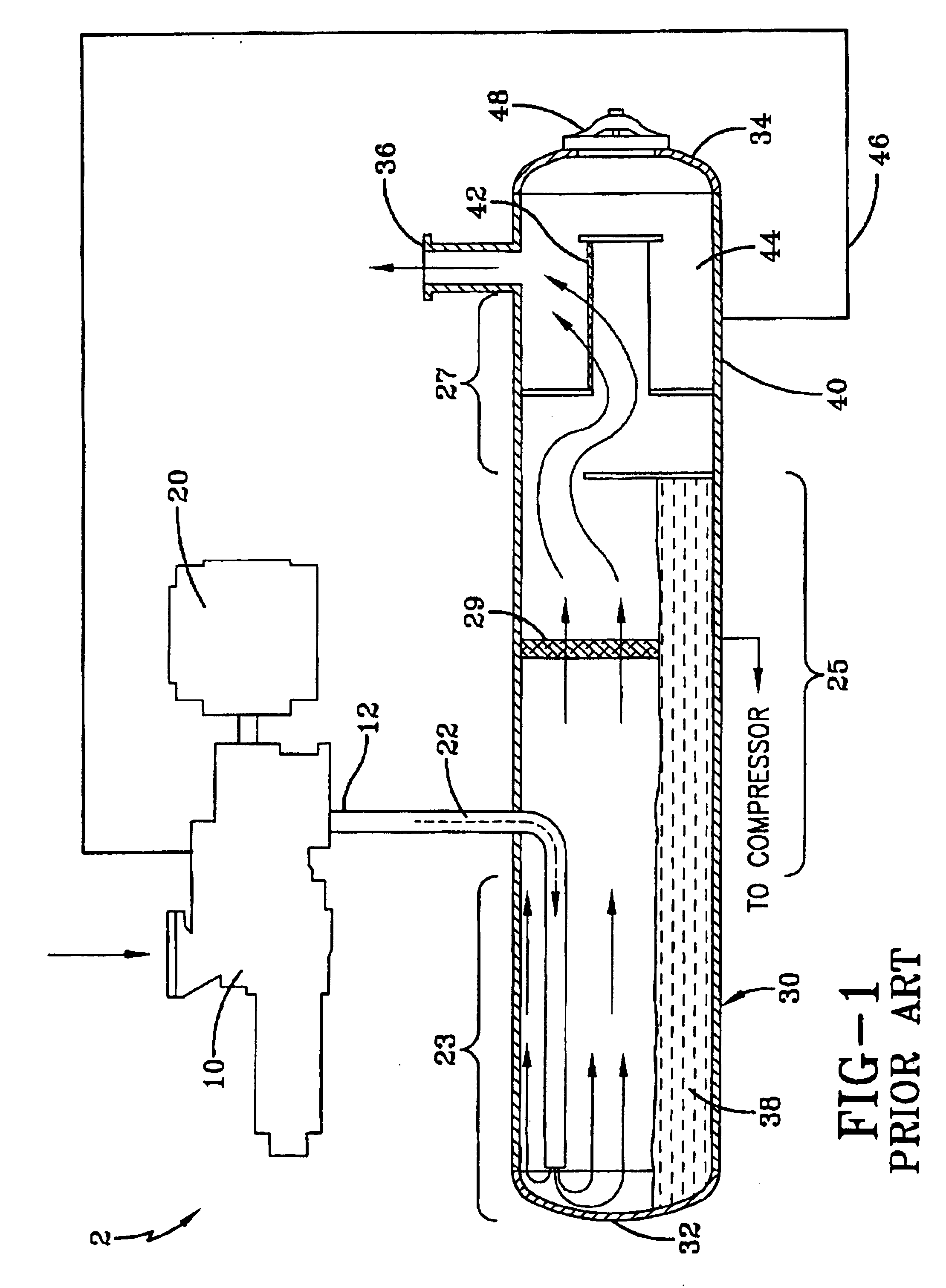
[0054]An embodiment of the present invention designed to operate with “smokeless” lubricant is set forth in FIG. 3. A schematic of a portion of an existing screw compressor of the present invention 202 shows the compressor 210, the motor 220 which may be integral with compressor 210 and a separator 230, which eliminates the third stage 27 and thus the coalescer portion 40 utilized in the prior art practice. FIG. 3 is illustrative and is not meant to limit the present invention to screw compressors or to a particular type of screw compressor, and can include male / female screw compressors, single screw compressors or any variations of screw compressor technology. Compressed gas and entrained lubricant exits compressor discharge port 212 and is carried by conduit 222 into separator 230. Separator 230 is a horizontal separator and includes a first head 232, a second head 234, and a discharge port 236. Within separator 230 are an optional vane mist eliminator 260 and mesh mist eliminator...

example 2

[0060]A second embodiment of the present invention designed to operate with “smokeless” lubricant is set forth in FIG. 5. This design is similar to the design set forth in FIG. 3, except that the reservoir for the agglomerated fluid is external to the separator. A schematic of a portion of an existing screw compressor of the present invention 402 shows the compressor 410, the motor 420 which may be integral with compressor 410 and a separator 430, which eliminates the third stage coalescer portion 40 utilized in the prior art practice. Compressed gas with entrained lubricant exit compressor discharge port 412 and are carried by conduit 422 into separator 430. Separator 430 is a horizontal separator and includes a first head 432, a second head 434, and a discharge port 436. Within separator are a vane mist eliminator 460 and a mesh mist eliminator 470. Compressed fluid traveling at high velocity entering the separator through conduit 422 exits the conduit as in the prior art design. ...

example 3

[0063]A third embodiment of the present invention designed to operate with “smokeless” lubricant is set forth in FIG. 6. This design is similar to the design set forth in FIG. 3, except that compressed fluid traveling at a high velocity upon entering separator 530 after leaving conduit 522 passes through a centrifugal separator 533 positioned immediately adjacent the conduit exit within separator 530. A schematic of a portion of an existing screw compressor of the present invention 502 shows the compressor 510, the motor 520 which may be integral with compressor 510 and a separator 530, which eliminates the third stage coalescer portion 40 utilized in the prior art practice. Compressed fluid comprising refrigerant and entrained lubricant exits compressor discharge port 512 and is carried by conduit 522 into separator 530. Separator 530 is a horizontal separator and includes a first head 532, a second head 534, and a discharge port 536. Compressed fluid traveling at high velocity ent...


PUM

PropertyMeasurementUnit
sizeaaaaaaaaaa
diameteraaaaaaaaaa
diameteraaaaaaaaaa

Abstract

A compression system including a compressor driven by a motor, an optional accumulator, a liquid / gas separator, heat exchangers in the form of a condenser and an evaporator, expansion valves and conduit in the form of piping to connect these components together. The liquid / gas separating means is a lubricant separator, typically a cylindrical horizontal or vertical vessel used in conjunction with a gas compressor. The lubricant separator accepts discharge flow from the compressor which includes a mixture of a “smokeless” lubricant and refrigerant gas in a range of particle sizes forming a fluid stream, separates the refrigerant gas from the lubricant and collects the lubricant for reuse in the compressor. Because the lubricant used in the lubrication system rapidly agglomerates into larger size droplets and does not produce an aerosol, the separator does not require a coalescer element to coalesce aerosol and does not require a manway for serving the coalescer element. The coalescer element is replaced with a more reliable and durable mesh pad to agglomerate the larger sized droplets. The overall size and space requirements associated with the separator are reduced.

Description

FIELD OF THE INVENTION[0001]The present invention is directed to compressor systems for use with smokeless lubricants, and specifically compressor systems utilizing positive displacement compressors with smokeless lubricants.BACKGROUND OF THE INVENTION[0002]Positive displacement compressors are machines in which successive volumes of air or gas are confined within a closed space and elevated to a higher pressure. The pressure of the gas is increased while the volume of the closed space is decreased. Positive displacement compressors include, for example, reciprocating compressors, rotary compressors, scroll compressors and screw compressors. Screw compressors, also known as helical lobe rotary compressors, including single screw compressors, male-female (double) screw compressors and other variations, are well-known in the air compressor, refrigeration, water chiller, and natural gas processing industries. These compressors rely on lubricating oil to lubricate rotating and contactin...

Claims


Application Information

Patent Timeline
Patent Type & Authority Patents(United States)
IPC IPC(8): B01D45/06B01D45/00B01D50/00F04C18/16F04C29/02F25B43/02
CPCB01D45/06B01D50/002F04C29/026F25B43/02F04C18/16F25B2400/02B01D50/20
Inventor BARRATT, THOMASMCQUADE, WILLIAM
Owner YORK INT CORP
Learn More