Fuel injection device

a fuel injection device and fuel flow path technology, which is applied in the direction of liquid fuel burners, lighting and heating apparatus, combustion types, etc., can solve the problems of sometimes coking of fuel for combustor use, and achieve the suppression of vibrational stress generated at the joining portion, the effect of further effectively suppressing heat input to the fuel flow path portion

Active Publication Date: 2020-04-07
KAWASAKI HEAVY IND LTD
View PDF27 Cites 3 Cited by
  • Summary
  • Abstract
  • Description
  • Claims
  • Application Information

AI Technical Summary

Benefits of technology

[0006]The present invention has been made in view of the above-described circumstances, and an object of the present invention is to provide a fuel injection device which includes a fuel injector of a plane jet type and in which coking in the fuel injector is effectively prevented.
[0015]In one embodiment of the present invention, the fuel injector may be a pilot fuel injector, and the fuel injection device may further include a main fuel injector encircling an outer circumference of the pilot fuel injector. According to this configuration, it becomes easy to optimally design the entire fuel injection device in which, for example, diffusion combustion and lean combustion are allocated to the pilot fuel injector and the main fuel injector thereby to achieve stable combustion and reduction in NOx, respectively, while coking in the pilot fuel injector is prevented.

Problems solved by technology

However, fuel for use in a combustor is sometimes coked when being subjected to a high temperature.

Method used


Image

  • Fuel injection device
  • Fuel injection device
  • Fuel injection device

Examples


Embodiment Construction

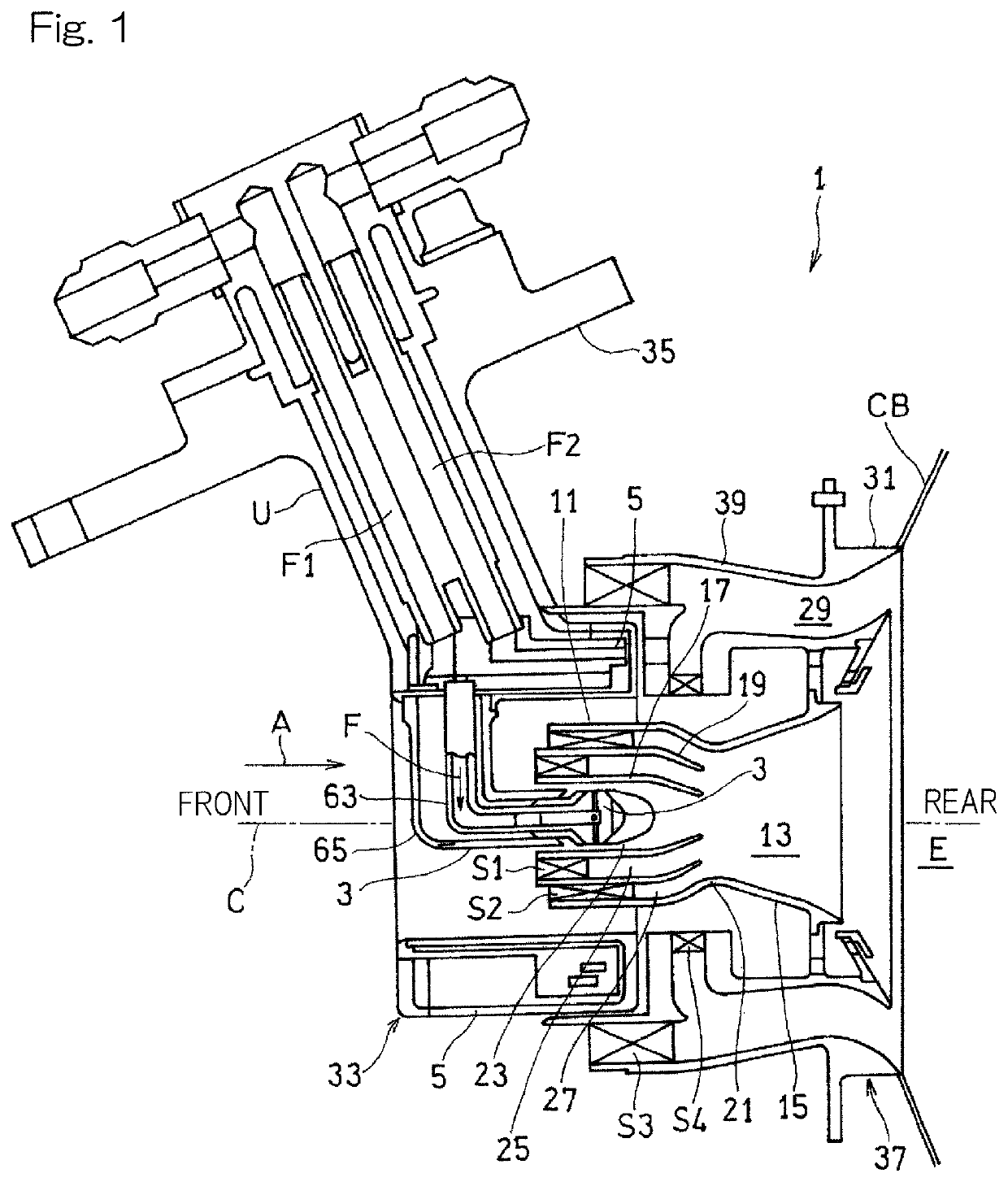
[0023]Hereinafter, an embodiment of the present invention will be described with reference to the drawings. FIG. 1 shows a fuel injection device 1 according to one embodiment of the present invention. The fuel injection device 1 is a device that is used in a combustor CB of a gas turbine engine for injecting, into a combustion chamber E of the combustor CB, a mixture of fuel F and compressed air A supplied from a compressor of the gas turbine engine. High-temperature and high-pressure combustion gas generated by combustion of the mixture in the combustion chamber E is supplied to a turbine to thereby drive a turbine. The fuel injection device 1 according to the present embodiment may be used for, for example, an annular type combustor CB, and a plurality of the fuel injection devices 1 may be arranged at equal intervals concentrically with the engine rotation axis which is not shown.

[0024]In the following description, the combustion chamber E side in an axis C direction of the fuel ...


PUM


Abstract

A fuel injection device for injecting an air-fuel mixture to a combustion chamber in a combustor of a gas turbine engine includes a fuel injector which is arranged on an axis of the fuel injection device. The fuel injector includes a fuel injection portion for injecting fuel in the radial direction of the fuel injection device, a fuel flow path portion forming a passage through which fuel is supplied to the fuel injection portion, and a heat shield cover that covers an end portion facing toward the combustion chamber side of the fuel injection portion such that an air layer is formed between the heat shield cover and the end portion.

Description

CROSS REFERENCE TO THE RELATED APPLICATION[0001]This application is a continuation application, under 35 U.S.C. § 111(a), of international application No. PCT / JP2016 / 088259, filed Dec. 22, 2016, which claims priority to Japanese Patent Application No. 2015-250354, filed Dec. 22, 2015, the disclosure of which are incorporated by reference in their entirety into this application.BACKGROUND OF THE INVENTIONField of the Invention[0002]The present invention relates to a fuel injection device used in a combustor of a gas turbine engine.Description of Related Art[0003]Conventionally, various types have been proposed for fuel injectors used for aircraft gas turbine combustors. As one type thereof, a fuel injector of a plane jet type that injects fuel in the radial direction is known (e.g., see Patent Document 1). The fuel injector of this type has a merit that the structure thereof can be simplified.RELATED DOCUMENTPatent Document[0004][Patent Document 1]: JP Laid-open Patent Publication No...

Claims


Application Information

Patent Timeline
Patent Type & Authority Patents(United States)
IPC IPC(8): F02C7/22F23R3/34F23D11/38F23R3/14F23R3/28F23R3/10
CPCF23R3/28F23R3/286F23R3/343F02C7/22F23R3/10F23R3/14F23D11/38F23D2202/00F23D2214/00
Inventor MATSUYAMA, RYUSUKENISHIURA, TAKEO
Owner KAWASAKI HEAVY IND LTD
Why Eureka
Try Eureka