Exhaust gas purification device

a purification device and exhaust gas technology, applied in physical/chemical process catalysts, metal/metal-oxide/metal-hydroxide catalysts, separation processes, etc., can solve problems such as air pollution, achieve the effect of suppressing the sintering of noble metals with each other, facilitating flow, and suppressing the degradation of catalysts

Active Publication Date: 2020-04-21
CATALER CORP
View PDF15 Cites 13 Cited by
  • Summary
  • Abstract
  • Description
  • Claims
  • Application Information

AI Technical Summary

Benefits of technology

[0007]Approaches involving supporting a noble metal catalyst on the above particulate filters have been studied in recent years with a view to further increasing purification performance. For instance, Patent Literature 1 discloses an exhaust gas purification catalyst in which platinum (Pt) and rhodium (Rh) as noble metal catalysts are supported separately inside a partition wall. Further, Patent Literature 2 discloses an exhaust gas purification catalyst in which a palladium (Pd) layer as a noble metal catalyst is disposed inside a partition wall, and a rhodium (Rh) layer is laid on the surface of the partition wall.
[0008]In the exhaust gas purification catalyst of Patent Literature 1, however, Pt and Rh are supported in the same manner from the inlet side to the outlet side, as viewed in the length direction of the substrate (axial direction of the substrate), from the exhaust gas inlet side towards the outlet side. Therefore, sintering (grain bonding) of Pt and Rh occurs when the catalyst is exposed to high temperature. The purification performance on exhaust gas may drop as a result. In the exhaust gas purification catalyst of Patent Literature 2, Pd and Rh are disposed inside and outside the partition wall, respectively, and thus sintering between Pd and Rh can be suppressed. The Rh layer is disposed outside the partition wall, however, and thus exhaust gas does not flow readily, and there is a greater loss of pressure (hereafter also referred to as pressure loss), which is a drawback. Conventional configurations have thus room for improvement as regards combining enhanced purification performance with reductions in pressure loss.

Problems solved by technology

Generally, exhaust gas emitted by internal combustion engines contains PM (particulate matter) having carbon as a main component, as well as ash made up of unburned components, which are known to give rise to air pollution.

Method used


Image

  • Exhaust gas purification device
  • Exhaust gas purification device
  • Exhaust gas purification device

Examples


example 1

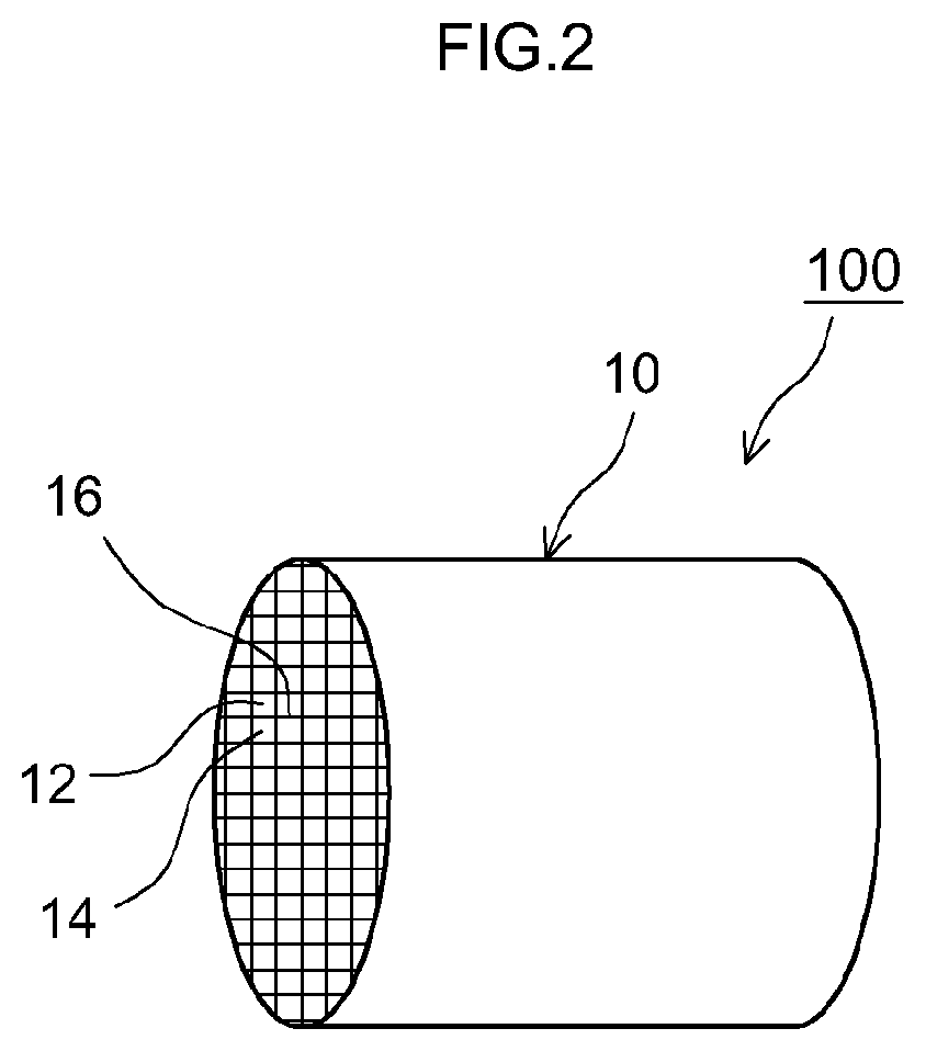
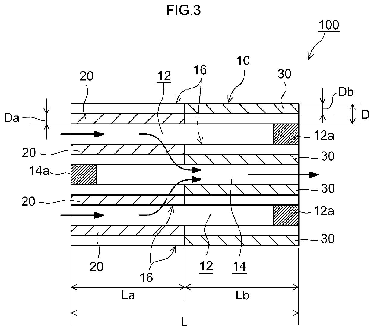
[0070]A particulate filter containing Pd in the upstream catalyst layer and containing Rh in the downstream catalyst layer was produced. Specifically, there was prepared ceria-zirconia complex oxide as a carrier for upstream catalyst layer formation. The ceria-zirconia complex oxide was impregnated with a solution of Pd nitrate, as a noble metal catalyst solution, followed by evaporation to dryness, to prepare a Pd / ceria-zirconia complex oxide carrier powder supporting 1.91 mass % of Pd. Then a slurry A was prepared by mixing 62.2 parts by mass of the Pd / ceria-zirconia complex oxide carrier powder, 36.61 parts by mass of alumina, 18.32 parts by mass of BaSO4, and deionized water. Next, this slurry A was applied through suction onto a portion of a cordierite substrate (wall-flow-type substrate illustrated in FIG. 2 and FIG. 3: diameter 103 mm, total length 100 mm) corresponding to 50% of the length L of the substrate from the exhaust gas inflow end section towards the downstream side...

example 2

[0072]A particulate filter was produced in the same way as in Example 1, but herein the coating amount of the upstream catalyst layer per L of volume of substrate was set to 60 g / L, the coating amount of the downstream catalyst layer per L of volume of substrate was set to 140 g / L, and the proportion of the coating amount of the upstream catalyst layer with respect to the total coating amount of the upstream catalyst layer plus the downstream catalyst layer was set to 30%.

example 3

[0073]A particulate filter was produced in the same way as in Example 1, but herein the coating amount of the upstream catalyst layer per L of volume of substrate was set to 80 g / L, the coating amount of the downstream catalyst layer per L of volume of substrate was set to 120 g / L, and the proportion of the coating amount of the upstream catalyst layer with respect to the total coating amount of the upstream catalyst layer plus the downstream catalyst layer was set to 40%.


PUM

PropertyMeasurementUnit
porosityaaaaaaaaaa
porosityaaaaaaaaaa
thicknessaaaaaaaaaa

Abstract

An exhaust gas purification device includes: a substrate of wall-flow structure having an inlet cell, an outlet cell and a porous partition wall; an upstream catalyst layer provided inside the partition wall and disposed in an upstream portion, including an exhaust gas inflow end section, of the substrate; and a downstream catalyst layer provided inside the partition wall and disposed in a downstream portion, including an exhaust gas outflow end section, of the substrate. The downstream catalyst layer contains a carrier, and Rh supported on the carrier. The upstream catalyst layer contains a carrier, and Pd and / or Pt supported on the carrier.

Description

TECHNICAL FIELD[0001]The present invention relates to an exhaust gas purification device. More particularly, the present invention relates to an exhaust gas purification device that purifies exhaust gas emitted by an internal combustion engine such as a gasoline engine.[0002]The present international application claims priority based on Japanese Patent Application No. 2016-077475, filed on Apr. 7, 2016, the entire contents of which are incorporated in the present description by reference.BACKGROUND ART[0003]Generally, exhaust gas emitted by internal combustion engines contains PM (particulate matter) having carbon as a main component, as well as ash made up of unburned components, which are known to give rise to air pollution. Regulations concerning emissions of particulate matter have therefore become stricter year after year, alongside regulations on harmful components in exhaust gas such as hydrocarbons (HC), carbon monoxide (CO), and nitrogen oxides (NOx). In this respect, vario...

Claims


Application Information

Patent Timeline
Patent Type & Authority Patents(United States)
IPC IPC(8): F01N3/022B01J23/63F01N3/28F01N3/035B01J35/04F01N13/00B01D53/94F01N3/021F01N3/10B01J35/00B01J37/02B01J23/46B01J23/44B01J23/42
CPCF01N3/105F01N3/022F01N3/035F01N3/2803F01N3/2828F01N3/021F01N3/101B01J37/0244F01N13/0097B01J23/464B01J23/63B01J35/0006F01N3/0222B01D53/9454B01J23/42B01D53/9472B01J35/04F01N3/2892B01J23/44B01D2257/404B01D2255/9032F01N2510/068B01D2255/904F01N2510/0682B01D2255/1026B01D2255/1028B01D2255/1021B01D2255/9155B01D2255/1023B01D2255/1025B01D2257/702B01D2257/502Y02T10/12
Inventor INODA, SATORUNOMURA, YASUTAKAKURIYAMA, JUNJIMIYOSHI, NAOTOTAKEUCHI, MASAHIKOSATO, AKEMI
Owner CATALER CORP
Why Eureka
Try Eureka