Systems and methods for distortion free multi beam ultrasound receive beamforming

a multi-beam ultrasound and beamforming technology, applied in ultrasonic/sonic/infrasonic image/data processing, instruments, etc., can solve the problems of signal distortion in beamforming, internal signal distortion, dynamic change of signal delay, etc., to achieve high speed and compromise the ability of accurate detection

Active Publication Date: 2020-05-05
ESAOTE
View PDF12 Cites 2 Cited by
  • Summary
  • Abstract
  • Description
  • Claims
  • Application Information

AI Technical Summary

Benefits of technology

[0024]The present invention demonstrates a receive focusing delay and sum beamforming utilizing a very high dynamic range and very low distortion. The conceptual aspects of the present invention is based on the equation (3), wherein the estimation of the I,Q-vectors (being I,Q-detection), is placed prior to the beamforming delay and sum stages, this will render the beamforming to be fundamentally distortion-less. In the equation (3), for simplicity, an infinite small time-delay delay resolution is assumed. In practice, interpolation on the digitalized receive signals, is mandatory, due to the practical limitations on the sample time of the digitalization of the received Rf-signals. Interpolation on the I,Q-vectors is to realize sufficient fine-delay-resolution, this relates to the dynamic range of the beamforming. A true fine delay of the signals is needed to prevent signal-distortion (to prevent different delay of the carrier and envelope of the signals), this must be performed by means of a true interpolation, wherein high performance interpolation is mandatory to prevent an additional signal distortion generated by interpolation stages itself. Straight forward up-sample interpolation, which is computationally more intensive for normal interpolation, is used because in the application of a multi-line beamforming, the interpolation results can be reused for each multi line, therefore the up-sample interpolation process actually pre-computes extra in between samples needed for the high resolution delay stages, wherein each multi-line beamforming can make use of the pre-computed interpolated I,Q-samples, the fact that each multi-line can use the pre-computed samples, makes it very computational efficient compared to the usage of a poly-phase interpolation scheme for each multi-line.

Problems solved by technology

However, in a dynamic receive focusing delay and sum beamforming technique, the signal delays are dynamically changing during the reception, as a result internal signal distortions become generated by the way of signal processing of the beamforming itself.
However, as phase rotations are computationally more effective, the phase rotation is not a true fine delay of the total-signal, but only a delay of the carrier part of the signal, the envelope of the signal is not fine delayed, this also results in the generation of signal-distortions in the beamforming.
High performance interpolation in the beamforming requires a considerable computational burden.
Poly phase interpolation is computationally more effective, but needs, in this case of ultrasound beamforming, a fine-delay control in each receive signal path, as a result, the signal processing of all the beamforming elements together becomes, at the end, very computationally intensive.
However, also here, internal signal distortions become generated by the changing fine delay at the up-sample control stages, of this type of dynamic receive focusing beamforming.
Also common practice is the processing of multiple dynamic receiving focusing ultrasound beams, related to one ultrasound transmit event, this technique provides faster image frame-rates, but at the expense of lateral artifacts or loss of lateral sharpness.
To realize a dynamic receive focusing multi-beam beamforming with a high performance fine-delay interpolation quality it becomes very computationally intensive.
The higher frequencies become more attenuated over depth then the lower frequencies, the effect is that at deeper locations the higher frequencies are severely attenuated, the high frequencies become hidden in the noise.
The presence of any kind of depth depending tracking filters after the traditional beamforming, will also result in internal signal distortion as a result of the traditional manner of delay and sum beamforming.
The frequency-domain beamforming of other than linear array, is still very complex.

Method used


Image

  • Systems and methods for distortion free multi beam ultrasound receive beamforming
  • Systems and methods for distortion free multi beam ultrasound receive beamforming
  • Systems and methods for distortion free multi beam ultrasound receive beamforming

Examples


Embodiment Construction

[0186]While multiple embodiments are described, still other embodiments of the described subject matter will become apparent to those skilled in the art from the following detailed description and drawings, which show and describe illustrative embodiments of disclosed inventive subject matter. As will be realized, the inventive subject matter is capable of modifications in various aspects, all without departing from the spirit and scope of the described subject matter. Accordingly, the drawings and detailed description are to be regarded as illustrative in nature and not restrictive.

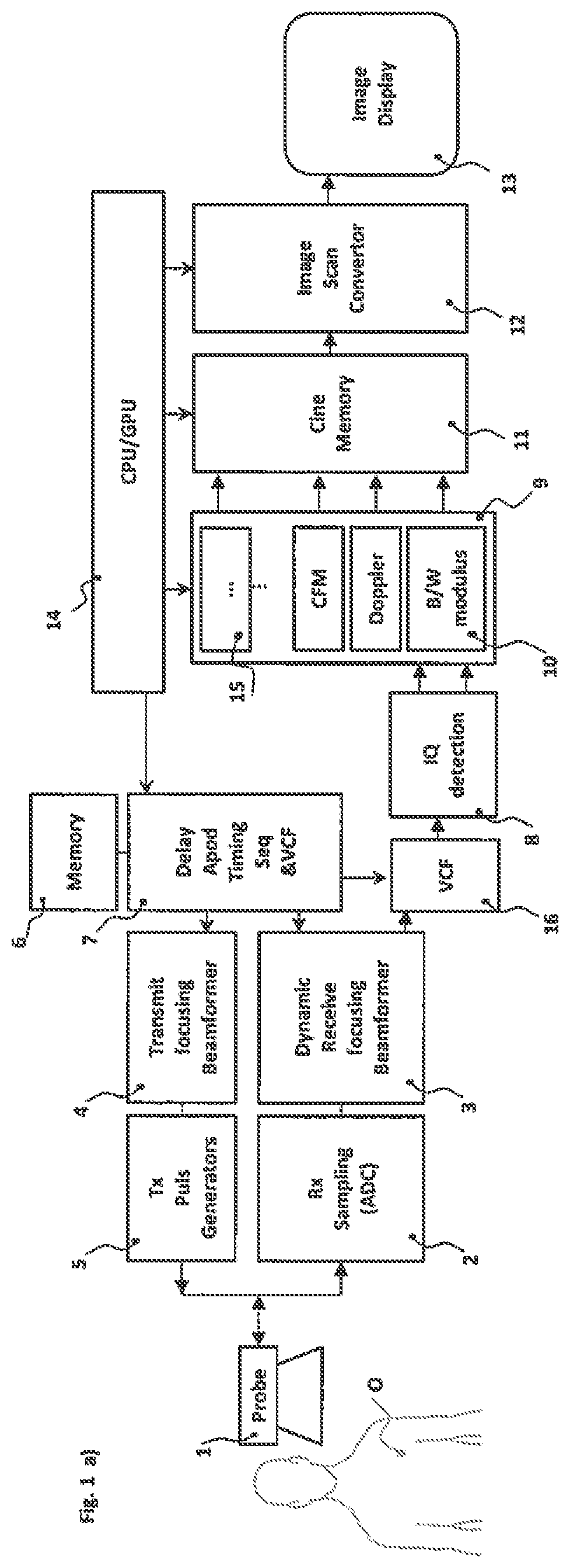
[0187]FIG. 1a shows an embodiment of an ultrasound system comprising the steps of: generation of transmit Rf-pulses by generator S with time profile information present in memory 6 being passed to a transmit focusing beam former 4 with a timing trigger control 7 creating a transmit beam profile being transmitted by means of an ultrasound probe 1 into an object O. Ultrasound waves travel through the objec...


PUM


Abstract

The present disclosure relates to an ultrasound multi line dynamic receive focusing beam former that is part of an ultrasound system, where the beam former of the present invention resolves conceptually the, in the prior art dynamic receive focusing beam formers, by fundament, internally generated distortions, which (in the prior art), become internally generated by the beam former process itself. These distortions within prior art beam formers, typically compromises, to some degree, the ability of accurate detections after the dynamic receive focusing beamforming. The present invention advantage is an ultrasound system capable of very accurate focusing selectivity with a high dynamic range, and very low signal distortion, therefore capable of, for example, a clear detection of harmonics and super harmonics, due to the fundamentally absence of internal distortion-generation. The scope is to resolve several, in prior-art, mentioned issues above, to provide computational efficient systems and methods capable of detecting the applications-features, very accurate and at high speed, utilizing the distortion free ultrasound Retrospective Transmit focus capable, multi-line dynamic receive focusing beamforming, which can be realized in hardware or software, wherein instead of 1d time domain processing, also 1d frequency domain processing might be utilized, suitable for other modalities that need longer detection lengths (like coding in Tx sequences).

Description

BACKGROUND OF THE INVENTION[0001]Ultrasound systems exist today that utilize a variety of techniques for processing ultrasound signals to generate information of interest. For example, a variety of techniques exist today for performing beamforming upon ultrasound receive signals. One approach to beamforming performs Rf-beamforming upon analog or digitalized receive signals. Another approach to beamforming performs baseband beamforming upon digitalized receive signals. In the technical field of diagnostic, ultrasound imaging it is common practice to perform receive focusing in a dynamic way during the reception of the ultrasound signals, this realizes a certain sharpness over a wider depth range. However, in a dynamic receive focusing delay and sum beamforming technique, the signal delays are dynamically changing during the reception, as a result internal signal distortions become generated by the way of signal processing of the beamforming itself.[0002]It is known in the technical f...

Claims


Application Information

Patent Timeline
Patent Type & Authority Patents(United States)
IPC IPC(8): G01S7/52G01S15/89G10K11/34A61B8/08
CPCG01S15/8977G01S7/52028G01S7/52095G10K11/346G01S15/8915G01S7/52077A61B8/5269A61B8/5207A61B8/52
Inventor PELLEGRETTI, PAOLOMULDER, THEODORUS FRANCISCUS
Owner ESAOTE
Why Eureka
Try Eureka