
Capacitive sensor element and method for the production thereof

a technology of capacitive sensor and production method, which is applied in the direction of capacitance measurement, instruments, computing, etc., can solve the problems of difficult economic and labor-intensive assembly and production method, and achieve the effect of producing inexpensively

Active Publication Date: 2020-05-05
POLYIC
View PDF26 Cites 0 Cited by
  • Summary
  • Abstract
  • Description
  • Claims
  • Application Information

AI Technical Summary

Benefits of technology

The present invention provides a sensor element with a specific arrangement of connections and conductive strips on the electrically conductive layers. The tolerance limit for the assembly of the two electrically conductive layers is set at the beginning, which allows for greater scope for the positioning of the individual layers. The invention is advantageous when printing the conductive strips and connections as a band-type support material of flexible plastic can be printed with conductive material in the roll-to-roll process. The technical effect of the invention is that it provides a cost-effective and efficient way to produce the sensor element with precise connections and conductive strips.

Problems solved by technology

This requirement of the production method is difficult to meet economically, which also makes assembly very expensive.

Method used


Image

  • Capacitive sensor element and method for the production thereof
  • Capacitive sensor element and method for the production thereof
  • Capacitive sensor element and method for the production thereof

Examples


Embodiment Construction

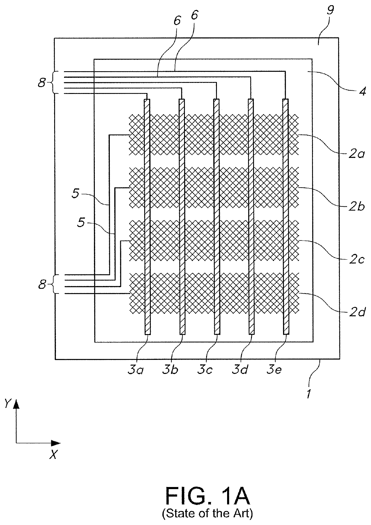
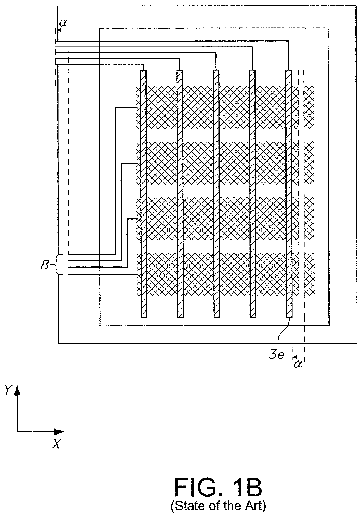
[0040]FIG. 1a shows a state of the art “bars” and “stripes” arrangement of conductive strips on two electrically conductive layers 2 and 3 lying one on top of the other, galvanically separated by a transparent dielectric insulating film 4, in different planes on a film support 1. The insulating film 4 here spans the whole transparent input area of the sensor element, which is surrounded by the edge area 9. In the edge area 9 lying outside the transparent input area the connections 5 and 6 of the conductive strips 2a . . . and 3a . . . lead to the connector plugs 8, via which a contact is made with a corresponding module. In order that the connections 5 and 6 engage with the plugs 8 making contact, the positions of the two electrically conductive layers must lie accurately one on top of the other. This is illustrated in FIG. 1b.

[0041]FIG. 1b shows a minimal register inaccuracy “a” when the individual layers of the two electrically conductive layers are laid, for example laminated, o...


PUM


Abstract

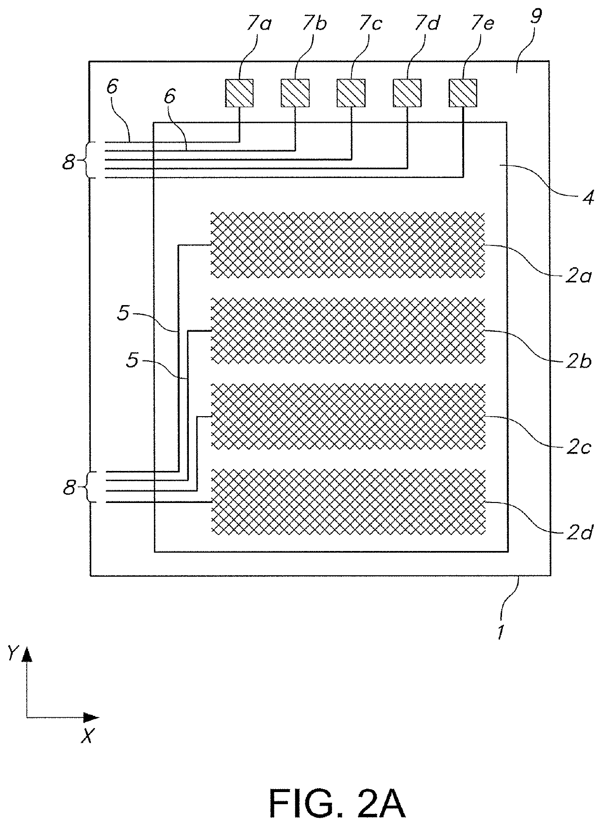
The invention relates to a capacitive sensor element with a plurality of sensor fields, as they correspond for example to the arrangement on a touch screen. This capacitive sensor element comprises at least one multilayer body made up of two structured electrically conductive layers and an insulating layer in between. The invention provides a layout with redundant conductive strips for an arrangement of crossing conductive strips, through which the requirement for register accuracy in the two-layer lamination of layer electrodes is reduced, in particular with respect to connecting the connections to the plugs in the edge area of a module using a corresponding sensor element.

Description

[0001]This application claims priority based on an International Application filed under the Patent Cooperation Treaty, PCT / EP2015 / 050175, filed on Jan. 7, 2015, and German Application No. DE 102014100246.6, filed on Jan. 10, 2014.BACKGROUND OF THE INVENTION[0002]The invention relates to a capacitive sensor element with a plurality of sensor fields, as they correspond for example to the arrangement on a touch screen. This capacitive sensor element comprises at least one multilayer body made up of two structured electrically conductive layers and an insulating layer in between. The invention also relates to a method for the production of such a sensor element.[0003]Such capacitive sensor elements are known from DE 10 2011 115 851 A1. The sensor elements disclosed therein comprise for example conductive strips arranged according to the “bar and stripe” principle as electrodes. For example, wide conductive strips, “bars” or bar electrodes, which run—again for example—in the x-direction...

Claims


Application Information

Patent Timeline
IPC IPC(8): G06F3/044
CPCG06F3/044G06F2203/04103G06F3/0445G06F3/0446G06F3/04164G01R27/2605G06F2203/04111
Inventor ULLMANN, ANDREASFIX, WALTERWALTER, MANFRED
Owner POLYIC
Learn More