Electronic status reporting circuit breaker

a technology of electronic status reporting and circuit breakers, applied in the direction of circuit breakers, instruments, process and machine control, etc., can solve the problems of circuit breakers, no information available, breaker will trip,

Active Publication Date: 2020-05-12
CARLING TECH
View PDF16 Cites 0 Cited by
  • Summary
  • Abstract
  • Description
  • Claims
  • Application Information

AI Technical Summary

Benefits of technology

[0018]It is still further desired to provide a circuit breaker that can query a circuit and connected load in a safe manner when the circuit interrupter is in either the off or tripped position and without the need of providing any additional wiring to the connected load.
[0020]These and other objects are achieved in one configuration by the provision of a circuit interrupter that includes a control circuit placed within the housing of the circuit interrupter and including a storage having data stored relating to electrical values for various signal characteristics. The control circuit is configured such that if the circuit interrupter is in either the off or tripped state (e.g., the contacts are open), the control circuit generates and transmits a test signal having a low current and low voltage onto the output of the circuit interrupter (the load terminal). The control circuit then measures the electrical values of the test signal and compares the measured signal to the saved information to determine if the measured signal exceeds a threshold deviation from the saved information. If so, then the circuit interrupter determines that the fault condition remains and can transmit this information via a network connection to a remote location. Additionally, the data relating to the measured signal can also be sent such that, rather than simply providing binary data (e.g., circuit shorted / circuit not shorted), the transmitted information can provide some intelligence as to the actual state of the circuit and connected load.

Problems solved by technology

If such a fault condition occurs in the electrical circuit, the breaker will trip.
This will cause a breaker that was in the “on” position to flip to the “off” position and interrupt the flow of electrical energy through the circuit breaker.
However, there is no information available as to what caused the overcurrent that caused the circuit breaker to trip, or whether or not the circumstance that led to the overcurrent still exists.
If the breaker immediately trips, the fault condition is still present.
However, applying voltage to the circuit to test to see if a fault condition is still present is not an optimal solution.
Additionally, in the event of a tripped circuit breaker, a technician will in all likelihood, have to physically inspect the circuit and connected loads.
If the circuit breaker trips, this tells the technician that a problem is likely with the wiring itself.
If the circuit breaker does not trip, then the problem is likely with one of the connected loads.
Again, applying a high voltage for testing purposes is not ideal.
However, this is a time consuming process, requires a technician to be on site to perform the testing and uses line voltage for testing purposes.
Another problem with the above approach is that no information beyond the fact that there is a fault that is causing the circuit breaker to trip, is obtained from the above-described method.
Still another problem is that, using a circuit breaker as a power switch or a diagnostic tool subjects the breaker to a greater number of operational cycles than it would otherwise experience in a typical circuit protection application.
This can result in an unacceptably premature failure of the circuit breaker.
This increases the cost of producing the circuit breaker.
Still another problem faced by loads that are connected to circuit breakers is that, circuit breakers are designed to trip once a current rating is exceeded.
As can then happen, eventually the load becomes more and more damaged until finally catastrophic failure of the load occurs, which then does cause an over current condition thereby causing the circuit breaker to trip.
However, the damage is done and the connected load is irretrievably damaged.

Method used


Image

  • Electronic status reporting circuit breaker
  • Electronic status reporting circuit breaker
  • Electronic status reporting circuit breaker

Examples


Embodiment Construction

[0039]Referring now to the drawings, wherein like reference numerals designate corresponding structure throughout the views.

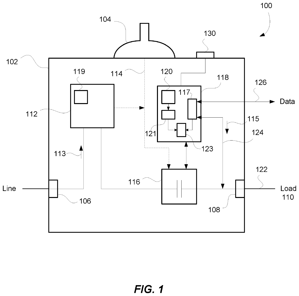
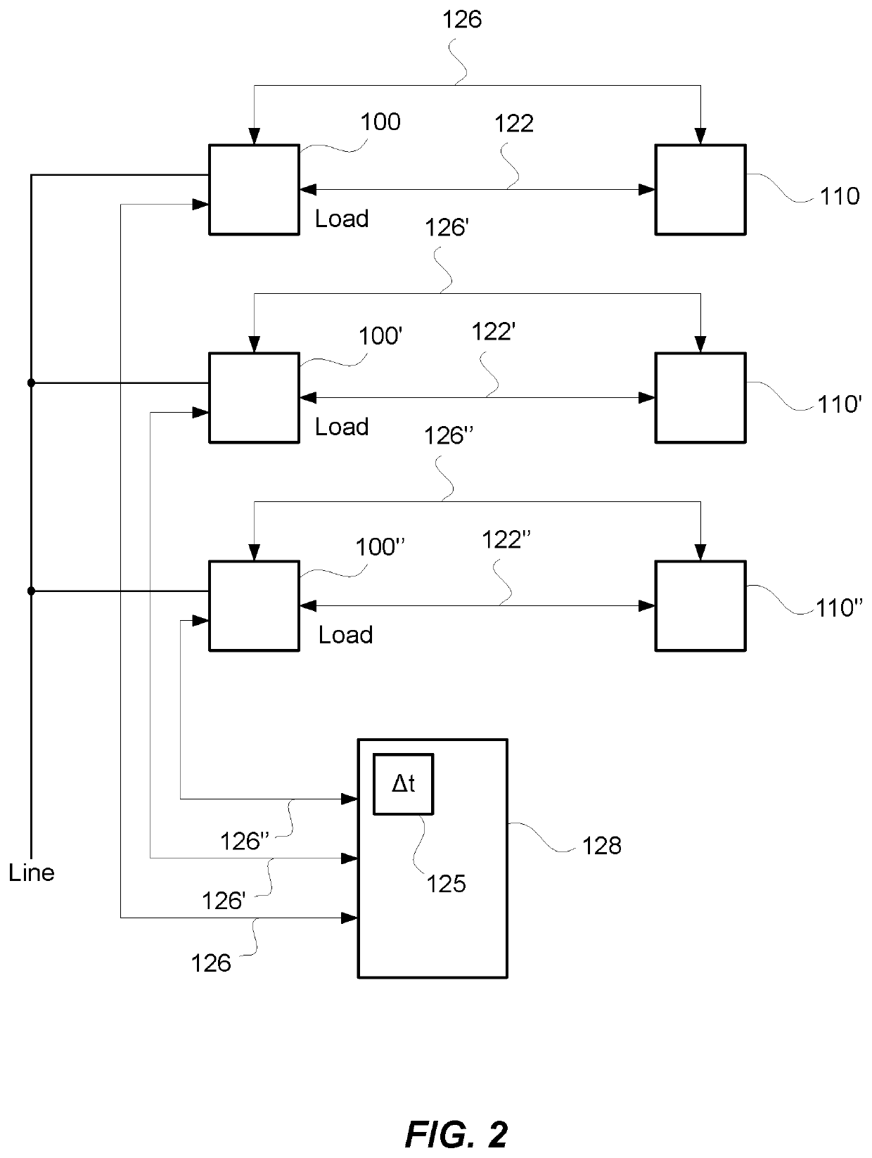
[0040]FIG. 1 depicts a circuit breaker 100 having a housing 102 with a handle 104. The circuit breaker could be any type of circuit breaker including, but not limited to having a line connection 106 that comprises a “stab” circuit breaker that includes two tines that connect to an electrical service bus bar in an electrical panel and a screw type connector comprising load connection 108 to be attached to a load 110 (FIG. 2); or line connection 106 could comprise a screw type connection for attaching to an electrical service bus bar in an electrical panel. There are numerous configurations that are possible and the above are just provided as two examples.

[0041]An overcurrent protection circuit 112 is provided that receives incoming power from line connection 106. Overcurrent protection circuit 112 is provided to measure the current 113 passing through the circui...


PUM


Abstract

A circuit breaker includes a control circuit capable of generating and transmitting a test pulse through its attached circuit and any connected load while its contacts are open, with the breaker in the OFF, or TRIPPED, state, to determine if detrimental anomalies exist, such as a short circuit. In certain configurations, the control circuit can measure and store a circuit's parameters for a properly operating load when the breaker is in the OFF state, and subsequently with the breaker in the OFF, or TRIPPED, state, compare the stored parameters to determine if an alarm condition exists and thereby initiate appropriate alerts and actions. In an alternate configuration, the breaker can be commanded to the OFF position by the load sending a signal through the power connection, with the breaker then being able to store the load's reason for shut-down and report such information to a remote location.

Description

FIELD OF THE INVENTION[0001]The invention relates to a circuit interrupter that is able to provide information when in an off or tripped state, and more specifically, the invention relates to a circuit breaker that monitors the status of a connected circuit and load when the circuit breaker is not providing electrical power to the load.BACKGROUND OF THE INVENTION[0002]Circuit interrupters are electrical components that can be used to break (or open) an electrical circuit, interrupting the current flow. A basic example of a circuit interrupter is a switch, which generally consists of two electrical contacts in one of two states; either closed, meaning that the contacts are touching and electricity can flow between them, or open, meaning that the contacts are separated, and no electricity can flow between them.[0003]Another example of a circuit interrupter is a circuit breaker. A circuit breaker may be used, for example, in an electrical panel to limit the electrical current being sen...

Claims


Application Information

Patent Timeline
Patent Type & Authority Patents(United States)
IPC IPC(8): H01H73/00H02H3/04H01H83/04H02J13/00H02H3/10H02H3/00G05B9/02H01H71/04H02H3/06H02H11/00
CPCH02H3/04H02J13/00007H01H71/04H02H3/10G05B9/02H02H3/006H01H83/04H02H3/066H02H11/005G01R31/00H02H1/0084Y04S10/18Y04S10/20Y04S40/121Y02E60/00
Inventor SORENSON, RICHARD W.
Owner CARLING TECH
Why Eureka
Try Eureka