
Serial data receiver with decision feedback equalization

Active Publication Date: 2020-05-12
APPLE INC
View PDF4 Cites 2 Cited by
  • Summary
  • Abstract
  • Description
  • Claims
  • Application Information

AI Technical Summary

Benefits of technology

The patent describes a circuit that can change the way it measures input voltage, based on a control signal. This allows for faster processing of certain data and longer valid windows for other data. The technology can improve the speed and reliability of data processing in electronic devices.

Problems solved by technology

Such circuits, however, may consume an undesirable amount of power, resulting in reduced battery life in a mobile computing device.

Method used


Image

  • Serial data receiver with decision feedback equalization
  • Serial data receiver with decision feedback equalization
  • Serial data receiver with decision feedback equalization

Examples


Embodiment Construction

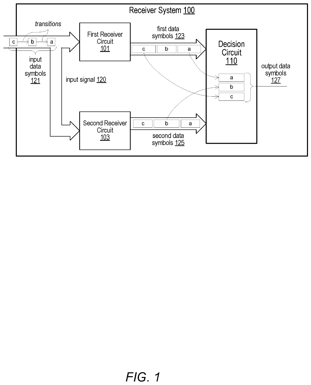
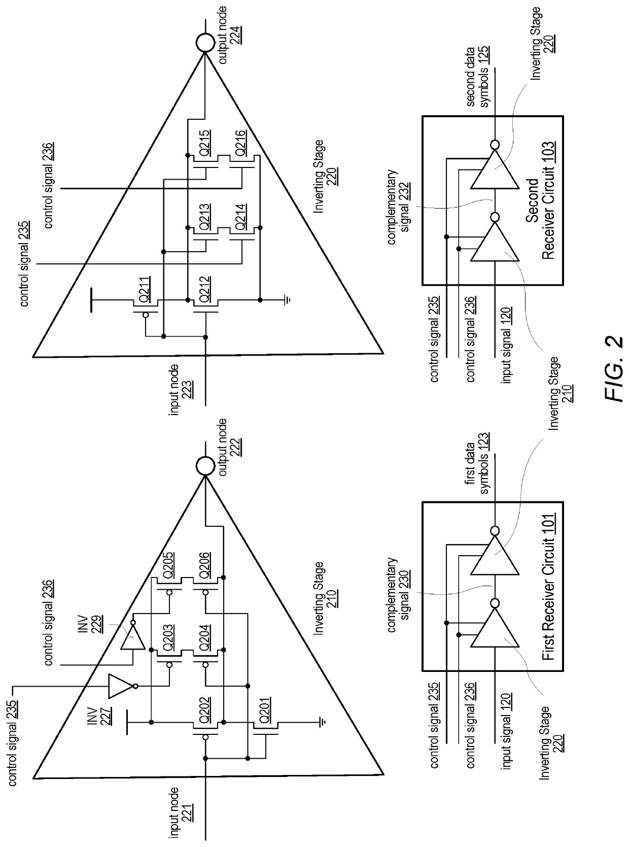
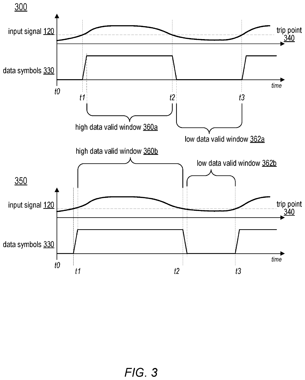
[0004]Broadly speaking, a system, an apparatus, and a method are contemplated in which the apparatus includes first and second receiver circuits and a decision circuit. The first receiver circuit may be configured to generate a first data symbol from a particular input data symbol of a plurality of input data symbols included in an input signal. The second receiver circuit may be configured to generate a second data symbol from the particular input data symbol. The decision circuit may be configured to select, using respective values of one or more previous output data symbols, either the first or second data symbol as a current output data symbol. In response to a change in value between successive input data symbols, the first and second receiver circuits may be configured to generate the first and second data symbols with respective data valid windows with different durations.

[0005]In a further example, to generate the first data symbol, the first receiver circuit may have a firs...


PUM


Abstract

An apparatus includes first and second receiver circuits and a decision circuit. The first receiver circuit is configured to generate a first data symbol from a particular input data symbol of a plurality of input data symbols included in an input signal. The second receiver circuit is configured to generate a second data symbol from the particular input data symbol. The decision circuit is configured to select, using respective values of one or more previous output data symbols, either the first or second data symbol as a current output data symbol. In response to a change in value between successive input data symbols, the first and second receiver circuits are configured to generate the first and second data symbols with respective data valid windows with different durations.

Description

BACKGROUNDTechnical Field[0001]Embodiments described herein are related to the field of integrated circuits, and more particularly to serial communication circuits in an integrated circuit.Description of the Related Art[0002]A computer system or integrated circuit, such as a system-on-a-chip (SoC), may include one or more interfaces for communication with other ICs. For example, an SoC may include a double-data rate (DDR) interface for communicating with a dynamic random-access memory (DRAM) module. As access times may directly impact performance of an SoC, there is a desire to transfer data between the SoC and the DRAM module as quickly as possible. DDR interfaces may, therefore, be designed for high data transfer frequencies.[0003]In combination with a desire for high performance computer systems, prevalence of mobile computing devices drives a desire for lower power computing systems, including low power DDR interfaces that operate at lower voltage levels. In order to receive hig...

Claims


Application Information

Patent Timeline
IPC IPC(8): H04L1/06H03K19/00H04L25/03
CPCH04L1/0643H03K19/0005H04L2025/0349H04L25/03343G06F13/4072H04L25/03878H03K5/22H03K19/018507Y02D10/00H04L25/03267G06F15/7807
Inventor KATAKWAR, MITESH D.LEE, SEONG HOONNGUYEN, HUY M.
Owner APPLE INC
Learn More