
Method and apparatus for repairing retaining walls

a technology for retaining walls and retaining rods, applied in the direction of building repairs, construction, building structures, etc., can solve the problems of system not providing any method of determining the necessary tension rod size and spacing, system simply not providing any information regarding, and no specific design parameters included. , to achieve the effect of greater load capacity

Active Publication Date: 2020-06-02
TAYLOR DIRK A
View PDF14 Cites 2 Cited by
  • Summary
  • Abstract
  • Description
  • Claims
  • Application Information

AI Technical Summary

Benefits of technology

[0015]For example, three different anchor and tension rod designs could be pre-designed for application to three different required tension rod tension loads of for example, up to 2,000 pounds, up to 4,000 pounds, and up to 8,000 pounds, thereby greatly simplifying the procedure for the contractor. The contractor simply selects which anchor and tension rod combination is the most appropriate for the wall condition and the calculated required anchor spacing based on the unit tension previously calculated.
[0016]The method and apparatus of the present invention for repairing retaining walls failing under lateral earth pressure is far superior to the prior art systems in that the method can be mathematically calculated and proven by accepted engineering standards, the system is much less expensive for installation and manufacture costs, no disturbances required to outside lawn, shrubbery or pavement, and the protrusion of the system into useable basement area is minimal. In addition, the system of the present invention is actually capable of ultimately moving the bowed wall back into its original straight and un-bowed condition over time, which is not possible by the aforementioned prior art systems.DISCUSSION OF RELATED PRIOR ART
[0019]The system design of the present invention is mechanically anchored to the masonry wall in a manner designed to ensure that the steel rods are only loaded in pure tension. To the contrary, the Ellis anchorage design results in both tension and bending loads being applied to the steel tension rods. The slender tension rods have the inherent ability to resist very high tension loads, but very little ability to resist bending loads. Therefore, when bending loads are considered, their tension load capacity is greatly reduced.
[0022]With the system of the present invention, like the bottom anchorage, the top anchorage of the system of the present invention is fastened to the masonry with positively connected masonry anchors that are specifically designed for each individual installation based on the actual existing conditions and provide much greater load capacity.

Problems solved by technology

The Ellis system does not provide any method of determining the necessary tension rod size and spacing, and also does not include any specific design parameters for the top and bottom anchorages.
The Ellis system simply does not provide any information regarding how to design the system for a given application.
To the contrary, the Ellis anchorage design results in both tension and bending loads being applied to the steel tension rods.
The slender tension rods have the inherent ability to resist very high tension loads, but very little ability to resist bending loads.
It is therefore held in place by friction and lever action that cannot be specifically designed for each individual installation and has an extremely limited load capacity.
Also, the top anchorage of the Ellis system is connected to the masonry wall with overlapped angles or hooks that are also held in place by friction and lever action that is not specifically designed for each individual installation and has an extremely limited load capacity.
In addition, the Ellis anchorages are more difficult to install and his upper anchorage is designed such that in many conditions his design cannot even be installed due to the fact that his upper anchorage is required to overlap the top of the failing masonry wall.

Method used


Image

  • Method and apparatus for repairing retaining walls
  • Method and apparatus for repairing retaining walls
  • Method and apparatus for repairing retaining walls

Examples


Embodiment Construction

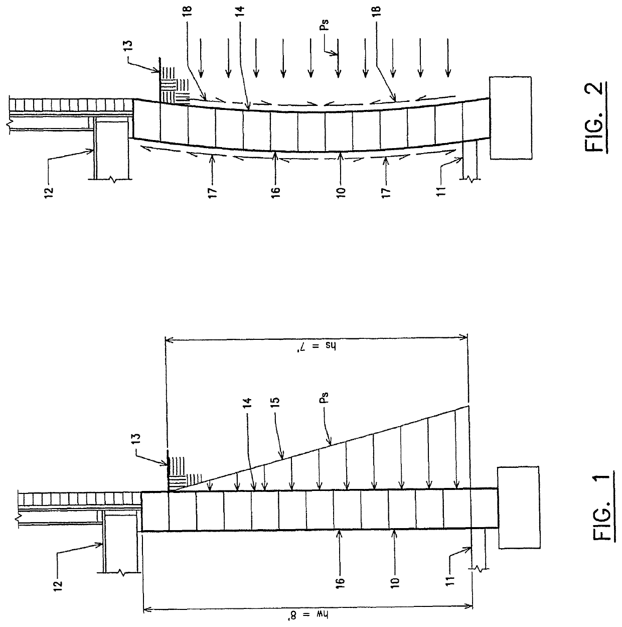
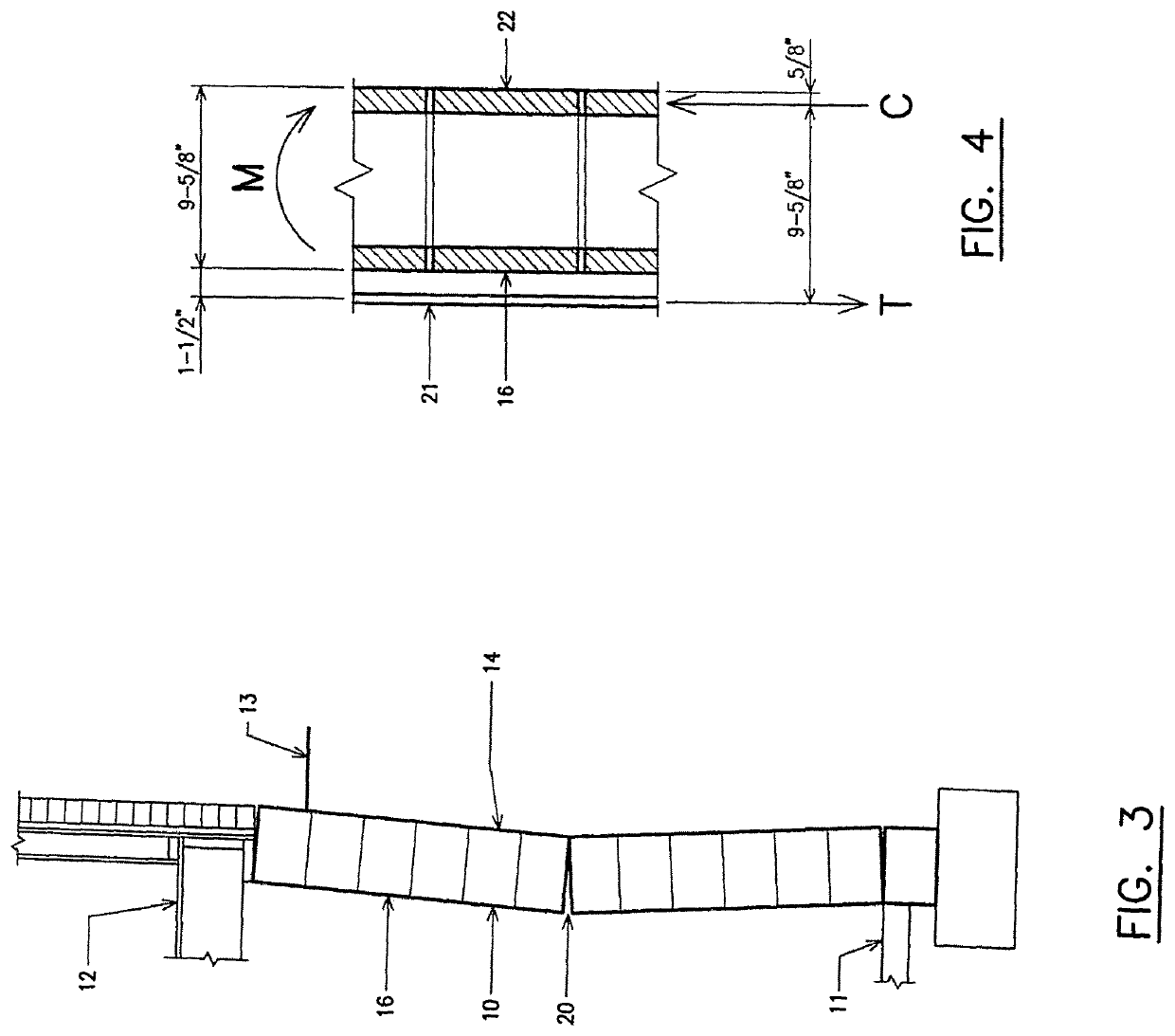
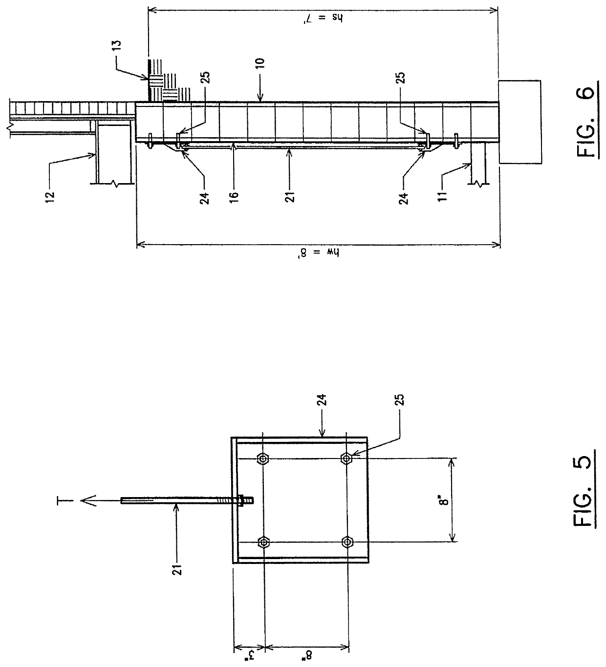
[0031]The system of the present invention is an improved method of repairing masonry and concrete retaining walls that are failing under lateral earth pressure. The system consists of a series of threaded steel tension rods anchored to the inner surface of a below grade (basement) retaining wall that is cracking and bowing inward as a result of lateral earth pressure applying horizontal force against the outer surface of that wall. It works by applying external tension forces to the inner wall surface to counteract calculated internal tension forces that have developed in the masonry or concrete as a result of bending from the lateral earth pressure, to stabilize the wall and correct the problem. Through proper design and installation, this system can even be used to re-straighten bowed walls back into their original “un-bowed” condition. While other wall repair systems claim to have the ability to straighten bowed walls, only the system of the present invention can truly perform th...


PUM


Abstract

A system for repairing masonry and concrete retaining walls that are failing under lateral earth pressure applied to the outer wall surface of the failing wall. Upper and lower spaced anchor plates are secured to the inner wall surface of the failing wall by respectfully securing the anchor plates to the inner wall surface with at least one anchor bolt. A threaded steel tension rod is then connected between the upper and lower anchor plates with nuts threadably secured to upper and lower ends of the rod. The threaded steel tension rod is placed under a desired tension load to thereby apply an external tension forced to the inner wall surface without applying bending stresses to the threaded steel rod by tightening at least one of the nuts.

Description

BACKGROUND OF THE INVENTION[0001]At the present time, specialty contractors typically employ one of three commonly used methods to repair cracked and bowed basement walls, depending upon the contractor's personal preference and experience, as well as the specific conditions involved with each installation. The three commonly used methods include earth anchors, vertical steel I-beams, and carbon fiber straps.[0002]Earth anchors consist of a series of steel plates positioned on the inner surface of a failing basement retainment wall. The plates are held in place by long steel tension rods that extend through pre-drilled holes in the wall to another steel plate buried in the soil outside the wall. This method requires considerable installation time and cost, and requires disruption to outside lawn, shrubbery or pavement. In addition, earth anchors are not supported by actual engineering design.[0003]Earth anchors rely on a design process that is fundamentally unsound from an engineerin...

Claims


Application Information

Patent Timeline
Patent Type & Authority Patents(United States)
IPC IPC(8): E04G23/02E04G23/04
CPCE04G23/0229E04G23/04
Inventor TAYLOR, DIRK A.
Owner TAYLOR DIRK A
Learn More