Ramping power in a wind turbine using gain scheduling

a wind turbine and gain scheduling technology, applied in the direction of engine control, motors, engine fuctions, etc., can solve the problems of unsatisfactory reduction in generator speed or generated power, and achieve the effect of improving the capability improving the control of the wind turbine, and high ramping ra

Active Publication Date: 2020-06-02
VESTAS WIND SYST AS
View PDF22 Cites 3 Cited by
  • Summary
  • Abstract
  • Description
  • Claims
  • Application Information

AI Technical Summary

Benefits of technology

[0007]It is an object of the invention to improve the control of a wind turbine in relation to handling power ramping demands, particularly to improve the wind turbine's capability to handle external power references which demands high ramping rates.
[0008]It is a further object of the invention to reduce undesired effects caused by fast ramping of power up to full production. Such undesired effects may include undesired reduction in generator speed or generated power.
[0009]It may a further object of the invention to reduce structural loads of the wind turbine due to power ramping demands.
[0014]The method for controlling a wind turbine may be used in a situation where the power production is increased or ramped up dependent on an increasing power reference. During ramping the pitch is controlled in order to adjust the power taken in by the rotor of the wind turbine so that the power taken in corresponds to the generated power. Due to dynamics the control system, the pitch may not be adjusted sufficiently fast. Advantageously, by increasing the gain for high rate of changes of the power reference, the dynamic capabilities of the control system may be improved so that the pitch may be adjusted faster with the effect that wind turbine is capable of tracking fast increases in the power reference.

Problems solved by technology

Such undesired effects may include undesired reduction in generator speed or generated power.

Method used


Image

  • Ramping power in a wind turbine using gain scheduling
  • Ramping power in a wind turbine using gain scheduling
  • Ramping power in a wind turbine using gain scheduling

Examples


Embodiment Construction

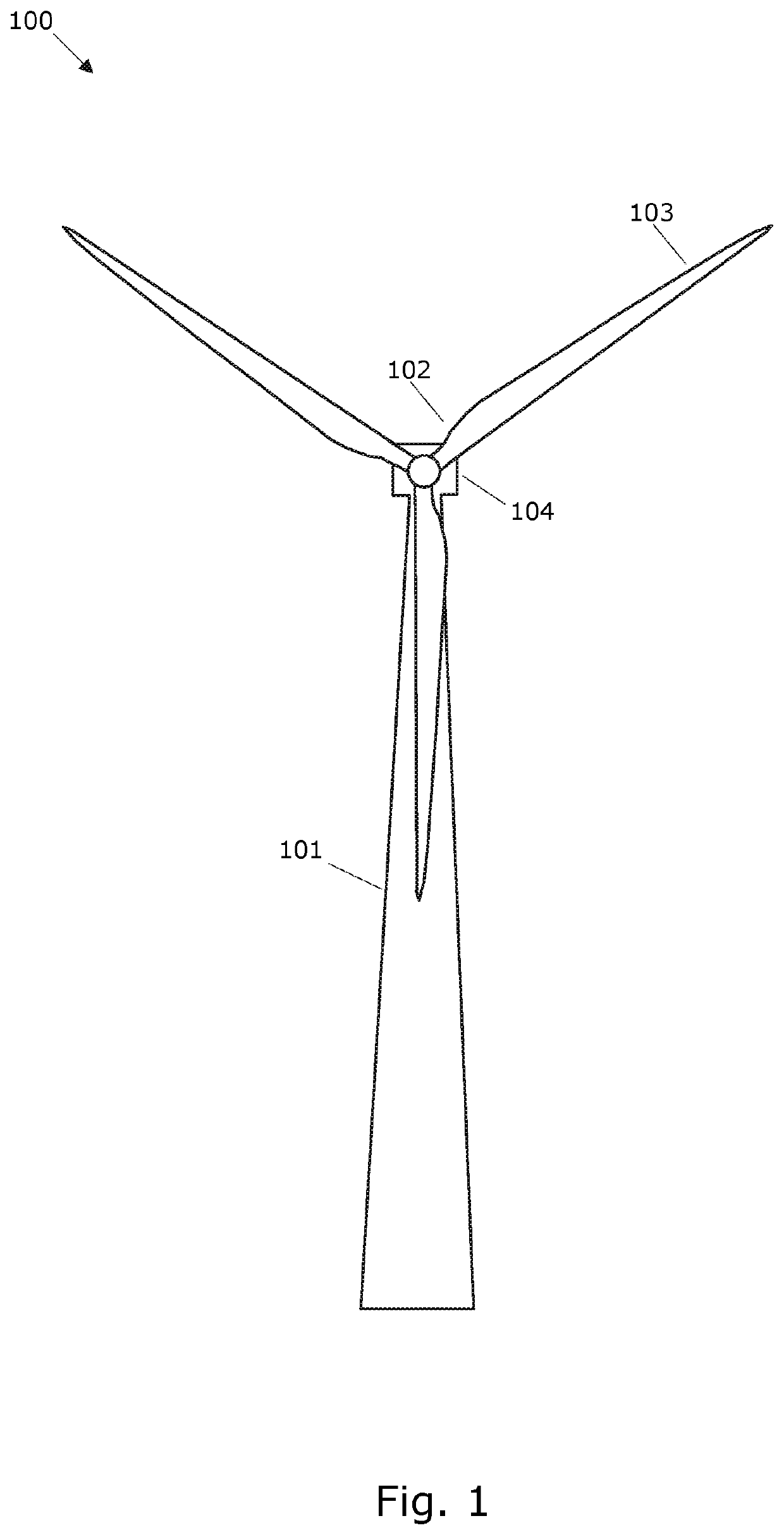
[0043]FIG. 1 shows a wind turbine 100 (WTG) comprising a tower 101 and a rotor 102 with at least one rotor blade 103, such as three blades. The rotor is connected to a nacelle 104 which is mounted on top of the tower 101 and being adapted to drive a generator situated inside the nacelle. The rotor 102 is rotatable by action of the wind. The wind induced rotational energy of the rotor blades 103 is transferred via a shaft to the generator. Thus, the wind turbine 100 is capable of converting kinetic energy of the wind into mechanical energy by means of the rotor blades and, subsequently, into electric power by means of the generator. The generator may include a power converter for converting the generator AC power into a DC power and a power inverter for converting the DC power into an AC power to be injected into a utility grid. The generator is controllable to produce a power corresponding to a power request.

[0044]The blades 103 can be pitched in order to alter the aerodynamic prope...


PUM


Abstract

The invention relates to a control system for a wind turbine. The wind turbine comprises a power generator configured to generate power dependent on a power reference and a pitch system configured to adjust the pitch of a blade of the wind turbine dependent on a pitch request. The control system comprises a controller configured to determine the pitch request dependent on an adjustable gain. A gain scheduler comprised by the control system is configured to set the adjustable gain to an increased gain value if a rate of change of the power reference, e.g. an external power reference, exceeds a threshold.

Description

FIELD OF THE INVENTION[0001]The invention relates to a method for controlling a wind turbine, particularly to a method for controlling a wind turbine during power ramping.BACKGROUND OF THE INVENTION[0002]Wind turbines may be operated in a de-rated mode where the wind turbine is controlled to produce an amount of power which is lower than the amount of power that can be produced considering the available wind power. The purpose of operating the wind turbine in a de-rated mode may be to establish a power reserve that can be released if needed.[0003]The de-rated wind turbine may be requested to ramp production up very fast to full production, e.g. in order to meet an increased power demand at the grid. The ramping demand may be in the form of an external power reference from a grid operator or other external source.[0004]The fast ramping of power up to full production may lead to various undesired effects such as undesired variations in the produced power.[0005]Accordingly, there is a ...

Claims


Application Information

Patent Timeline
Patent Type & Authority Patents(United States)
IPC IPC(8): F03D7/02
CPCF03D7/028F03D7/0224F03D7/0284F05B2270/309F05B2270/1033F05B2260/74F05B2270/335Y02E10/723F05B2260/71Y02E10/72
Inventor KJÆR, MARTIN ANSBJERGTHOMSEN, JESPER SANDBERGKRISTOFFERSEN, JACOB KROGHGRUNNET, JACOB DELEURANHERBSLEB, EIK
Owner VESTAS WIND SYST AS
Why Eureka
Try Eureka