Enhanced high aspect ratio etch performance using accelerated neutral beams derived from gas-cluster ion beams

a technology of accelerated neutral beams and high aspect ratio, which is applied in the direction of manufacturing tools, lapping machines, instruments, etc., can solve the problems of impracticality in the range, achieve the effect of maintaining critical dimensional tolerance, minimizing side wall damage, and mitigating the need for high concentration backgrounds

Active Publication Date: 2020-06-02
EXOGENESIS CORP
View PDF43 Cites 1 Cited by
  • Summary
  • Abstract
  • Description
  • Claims
  • Application Information

AI Technical Summary

Benefits of technology

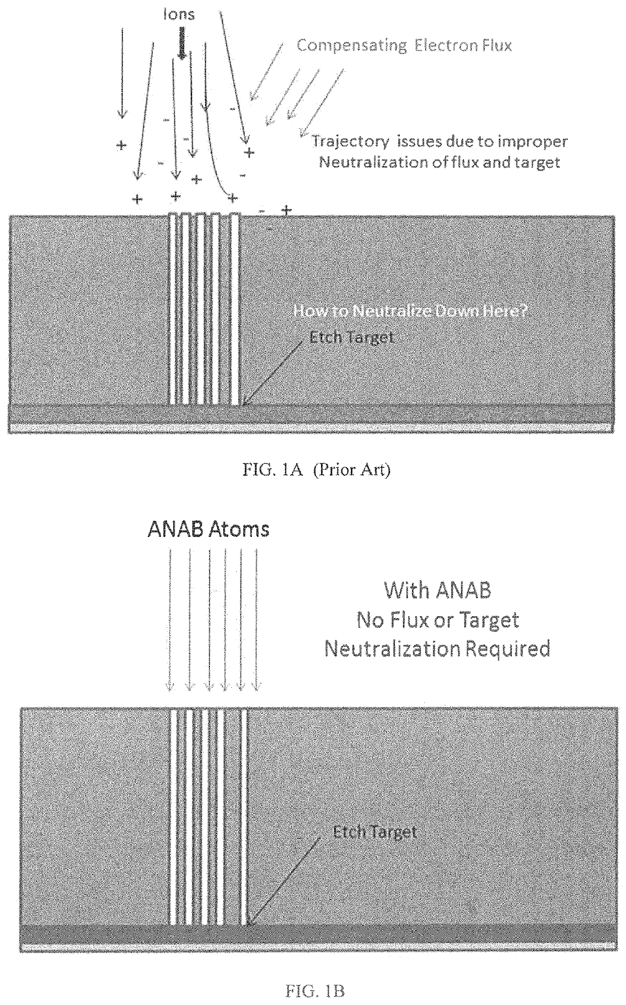
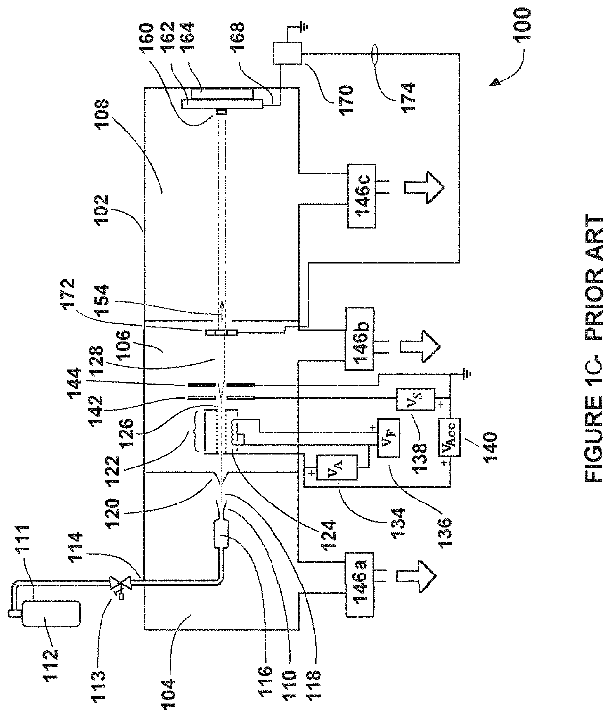
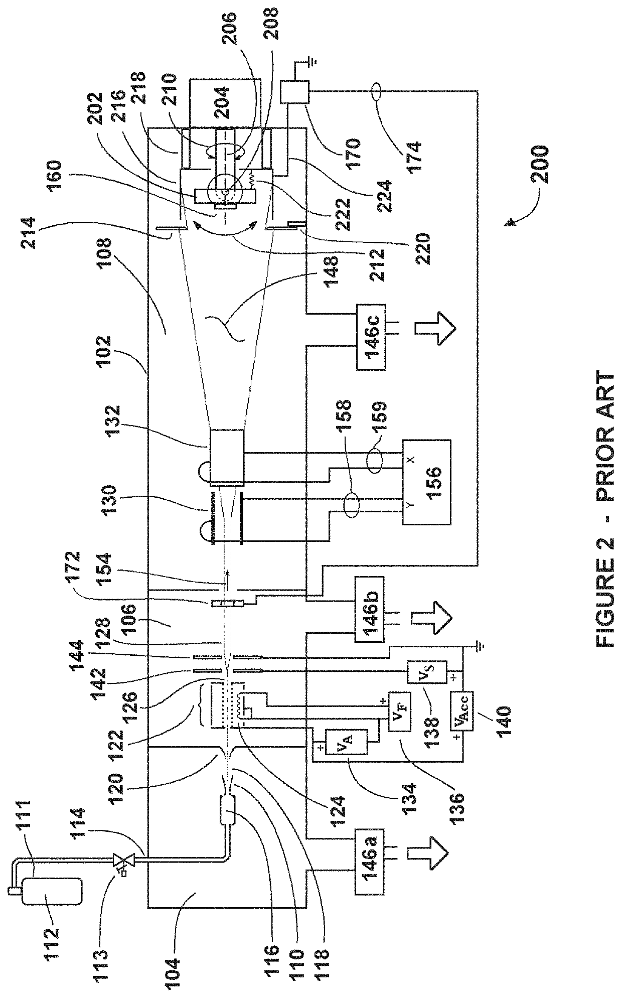
[0006]U.S. Pat. Nos. 8,847,148 and 8,629,393, both incorporated herein by reference, teach respectively methods and apparatus for generation of accelerated neutral beams derived from accelerated and dissociated gas-cluster ion beams, hereinafter sometimes referred to as “ANAB.” ANAB can provide intense, highly collimated beams of neutral (non-ionized) monomers with adjustable and controllable energies in the range from less than 10 eV to greater than a few hundred eV that are particularly well suited for high aspect ratio etching applications for the following reasons: ANAB are not subject to charge repulsion effects and can be transported long distances in highly collimated low divergence fashion. This is advantageous for processing at the bottom of high aspect features while minimizing side wall damage and maintaining critical dimensional tolerances. Any condensable gaseous species may be incorporated into ANAB to be delivered in into high aspect ratio features, thereby mitigating the need for high concentration backgrounds of hazardous or corrosive gases, minimizing attack on tool materials and increasing safety. Halogens, for examples, Cl2, F2, NF3 and SF6 alone or in combination with other species such as N2, O2, and CH4 are readily incorporated into source gases for ANAB generation to form ANAB comprising reactive constituents. ANAB can process both conductive and insulating layer materials without need for neutralization measures. This greatly simplifies processing and provides for highly repeatable, damage free processing (see FIG. 1B).

Problems solved by technology

This is an energy range in which it has been impractical with simple, relatively inexpensive apparatus to form intense neutral beams.

Method used


Image

  • Enhanced high aspect ratio etch performance using accelerated neutral beams derived from gas-cluster ion beams
  • Enhanced high aspect ratio etch performance using accelerated neutral beams derived from gas-cluster ion beams
  • Enhanced high aspect ratio etch performance using accelerated neutral beams derived from gas-cluster ion beams

Examples


Embodiment Construction

[0033]ANAB average energies per monomer and ANAB fluxes may be characterized by using a fixed orifice device that combines a thermopile to measure total power carried by the beam and an ion gauge pressure sensor calibrated for mass flow to measure the arriving monomer flux.

[0034]Three approaches are available for controlling the average energy of ANAB monomers.

[0035]The first is to control the size distribution of the clusters from which the ANAB monomers are generated. Cluster size can be altered by varying the flow of gas through the nozzle, with higher gas flows producing larger cluster sizes. As an example, if a 1000 monomer cluster is accelerated to 30 keV, then the energy per monomer is 30 eV. Similarly, if a 2000 monomer cluster is accelerated to 30 keV, then the energy per monomer will be 15 eV.

[0036]The second method for controlling average ANAB monomer energy is to vary the accelerating field voltage. A third approach to controlling average energy is by varying the nozzle ...


PUM

PropertyMeasurementUnit
particle energiesaaaaaaaaaa
energyaaaaaaaaaa
energyaaaaaaaaaa

Abstract

A method of processing a trench, via, hole, recess, void, or other feature that extends a depth into a substrate to a base or bottom and has an opening with high aspect ratio (into depth from opening to base or bottom divided by minimum space of the trench therebetween) by irradiation with an accelerated neutral beam derived from an accelerated gas cluster ion beam for processing materials at the base or bottom of the opening.

Description

RELATED APPLICATIONS[0001]This application claims priority from Provisional Application No. 62 / 519,389, filed Jun. 14, 2017 and is a continuation-in-part of U.S. patent application Ser. No. 14 / 466,242, filed Aug. 22, 2014, which is in turn a continuation-in-part of PCT / US13 / 27515, filed Feb. 2, 2013 which in turn claims benefit of U.S. Provisional Applications 61 / 601,980, filed Feb. 22, 2012; 61 / 650,747, filed May 23, 2012 and 61 / 658,522, filed Jun. 12, 2012. The present application is a continuation-in-part of U.S. patent application Ser. No. 14 / 466,242, filed Aug. 22, 2014, which is a continuation-in-part of U.S. patent application Ser. No. 13 / 215,514, filed Aug. 23, 2011, which claims priority of U.S. Provisional Applications 61 / 376,225, filed Aug. 23, 2010; 61 / 473,359, filed Apr. 8, 2011; 61 / 484,421, filed May 10, 2011; and 61 / 490,675, filed May 27, 2011. The entire contents of all these applications being incorporated herein by reference as though set out at length herein.BACKG...

Claims


Application Information

Patent Timeline
Patent Type & Authority Patents(United States)
IPC IPC(8): H01J37/00H01L21/265H01L21/02G03F1/82H05H3/02H01J37/147H01J37/05H01J37/32G03F1/80H01J37/317H01L21/311B24B37/04H01L29/36
CPCH05H3/02H01J37/05H01L21/02252H01L21/31111H01L21/31105H01L21/31116H01L21/26506H01J37/317H01L21/02274G03F1/80H01L21/26513G03F1/82H01L21/02115H01J37/3171H01J37/32816H01J37/147H01L21/02238H01L21/26566Y10T428/24479Y10T428/24355H01J2237/0041H01J2237/15H01J2237/0812Y10T428/30B24B37/04H01L29/36
Inventor KIRKPATRICK, SEAN R.CHAU, KIET A.CHAU, SON T.
Owner EXOGENESIS CORP
Why Eureka
Try Eureka