Battery system for vehicle

a battery system and vehicle technology, applied in battery/fuel cell control arrangement, safety/protection circuit, electric devices, etc., can solve the problems of reducing the voltage applied to affecting the operation of the electronic control unit, and affecting the performance of the auxiliary battery, so as to suppress the voltage drop

Active Publication Date: 2020-06-09
TOYOTA JIDOSHA KK
View PDF6 Cites 1 Cited by
  • Summary
  • Abstract
  • Description
  • Claims
  • Application Information

AI Technical Summary

Benefits of technology

[0006]According to the battery system, when the vehicle collides, the first electronic control unit turns off the first relays and interrupts electric power supply to the first electric loads. Interruption of electric power supply from the auxiliary battery to the first electric loads does not pose any particular problem. Meanwhile, as the first electronic control unit keeps the second relay turned on when the vehicle collides, an electric connection between the auxiliary battery and the first electronic control unit is maintained. As a result, while the electric power of the auxiliary battery is not supplied to the first electric loads, the electric power of the auxiliary battery is supplied to the first electronic control unit. This makes it possible to suppress the situation where the voltage applied to the first electronic control unit considerably decreases with respect to the power supply voltage of the auxiliary battery (the voltage when electric power supply from the auxiliary battery is not performed). Therefore, it is possible to suppress decrease in the voltage that is applied to the electronic control unit that requires the electric power from the auxiliary battery when the vehicle collides. Therefore, even after the vehicle collides, the electronic control unit continues to appropriately operate.
[0009]In the technique disclosed in the present disclosure, the auxiliary battery does not supply electric power to the first electric loads after a collision of the vehicle. Accordingly, the supply current is kept low, and so the decrease in the voltage that is applied to the electronic control unit after the collision of the vehicle is suppressed. This increases the opportunity that the electronic control unit continues to properly operate.
[0012]The technique described in the present disclosure utilizes the fact that the operation of some of the first electric loads that receive electric power supply from the auxiliary battery may be restricted without any problems after a collision of the vehicle, and therefore stopping the electric power supply to such first electric loads increases the possibilities of being able to secure the voltage applied to the electronic control unit.
[0014]The battery system for a vehicle can suppress the decrease in the voltage that is applied to the electronic control unit that requires electric power from the auxiliary battery when the vehicle collides, and therefore can continue to appropriately operate the electronic control unit even after the vehicle collides.

Problems solved by technology

When a vehicle collides, an auxiliary battery may be damaged, so that the performance of the auxiliary battery may deteriorate.
For example, a cell inside the auxiliary battery may be damaged, so that the voltage of the auxiliary battery may decrease.
In the technique of JP 2014-141112 A, when the vehicle collides, the voltage applied to the electronic control unit may decrease and the battery system may fail to operate appropriately due to such reasons as decrease in the battery voltage or increase in the internal resistance of the auxiliary battery when the auxiliary battery is not supplying electric power.
On the contrary, the first electronic control unit is an element such that restricted operation is not desirable when the vehicle collides.
That is, the first electronic control unit is an element such that interruption of electric power supply from the auxiliary battery is not desirable when the vehicle collides.
Accordingly, continuous operation of the first electric loads is failed.

Method used


Image

  • Battery system for vehicle
  • Battery system for vehicle

Examples


Embodiment Construction

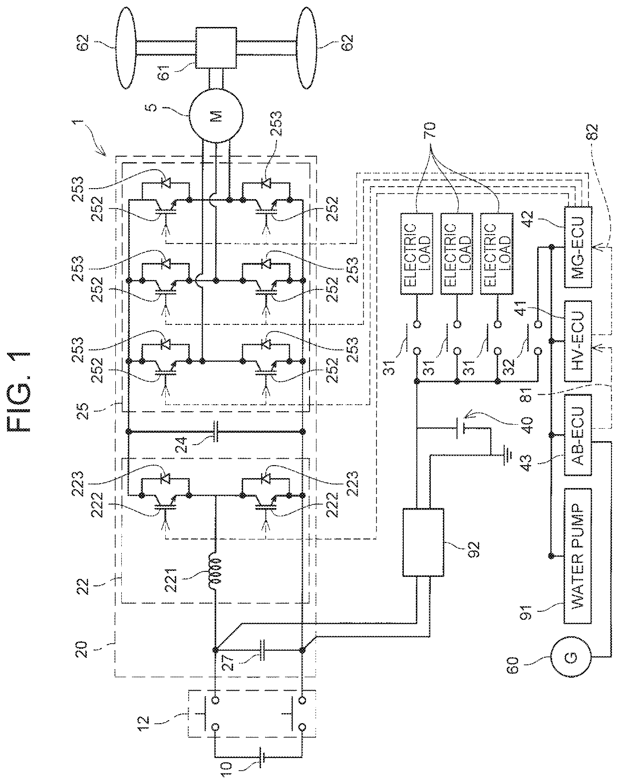
[0018]A battery system 1 for a vehicle according to an embodiment as one example of the present disclosure will be described with reference to the drawings. As illustrated in FIG. 1, the battery system 1 includes a main battery 10, a system main relay 12, a power control unit (PCU) 20, and a motor 5 for the vehicle. The battery system 1 includes an auxiliary battery 40, a plurality of electric loads 70, a hybrid vehicle-electronic control unit (HV-ECU) 41, a motor generator-electronic control unit (MG-ECU) 42, an air bag-electronic control unit (AB-ECU) 43, a water pump 91, and an acceleration sensor (referred to as a G sensor below) 60.

[0019]The battery system 1 illustrated in FIG. 1 is mounted, for example, on a hybrid vehicle (illustration omitted). The hybrid vehicle is a vehicle that travels with an electric motor and an unillustrated gasoline engine as power sources. The vehicle mounted with the battery system 1 may be a motor vehicle that does not include the gasoline engine....


PUM


Abstract

A battery system for a vehicle includes an auxiliary battery, first electric loads electrically connected to the auxiliary battery through first relays, a first electronic control unit electrically connected to the auxiliary battery through a second relay, the first electronic control unit being configured to turn on and off at least the first relays and the second relay, and a collision detection device configured to transmit a collision detection signal to the first electronic control unit when detecting a collision of the vehicle. The first electronic control unit is configured to switch the first relays from on to off, while keeping the second relay turned on when receiving the collision detection signal.

Description

CROSS-REFERENCE TO RELATED APPLICATIONS[0001]This application claims priority to Japanese Patent Application No. 2017-019432 filed on Feb. 6, 2017, which is incorporated herein by reference in its entirety.BACKGROUND1. Technical Field[0002]The technique disclosed in this specification relates to a battery system for a vehicle.2. Description of Related Art[0003]A battery system for a vehicle disclosed in Japanese Patent Application Publication No. 2014-141112 includes an auxiliary battery, an electric load electrically connected to the auxiliary battery through a first relay, and a controller electrically connected to the auxiliary battery through a second relay.SUMMARY[0004]When a vehicle collides, an auxiliary battery may be damaged, so that the performance of the auxiliary battery may deteriorate. For example, a cell inside the auxiliary battery may be damaged, so that the voltage of the auxiliary battery may decrease. Or internal resistance of the auxiliary battery may increase. ...

Claims


Application Information

Patent Timeline
Patent Type & Authority Patents(United States)
IPC IPC(8): B60L3/00H02P27/08H02J7/00H02J7/34B60L58/20
CPCH02J7/0029B60L58/20B60L3/0007H02J2310/48Y02T10/7005Y02T10/7066H02J7/345B60L2260/44Y02T10/70H02J7/007188
Inventor IKEYAMA, TOSHIO
Owner TOYOTA JIDOSHA KK
Why Eureka
Try Eureka